 WIFI Shield for Arduino
Dexter Industries WIFI Shield for Arduino
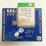
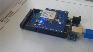
Dexter Industries WIFI Shield for the Arduino has been tested to work with the Uno , Mega, and Leonardo. The shield communicates with the Arduino over serial lines.
The WIFI shield is powered by the Gainspan GS1011 Module. We have developed an extensive library with examples serving web pages, creating web client and web server, reading Twitter timelines, posting to Cosm feeds, and communicating over TCP/IP. You can download the examples, library, and documentation here.
Contents [Hide]
Hardware
The Dexter Industries Wifi Shield is powered by the Gainspan GS1011 module. Through pins 12 and 13, the Arduino sends serial commands to send and receive data. Commands for connecting to a network and handling communications are built into our library. The Wifi shield comes configured with the following pins connected:
- 10 – RTS – Ready to send.
- 11 – CTS – Clear to send.
- 12 – RX – Receive
- 13 – TX – Transmit
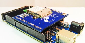
The image to the right shows a Wifi Shield in its default configuration.
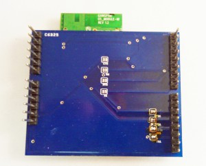
The shield comes with a second pinning configuration for advanced users. This can be used in the event that there is a conflict between pins in your project. The shield configuration can be changed with the solder jumpers on the underside of the shield. The alternate configuration is as follows:
- 4 – RTS
- 5 – CTS
- 6 – RX
- 7 – TX
Hardware Downloads:
Software
Below we have outlined the examples and the details of the library.
- For use with the Dexter Industries’ WIFI Shield for Arduino.
- The library and examples are compatible with Arduino version 1.0.1
Examples
TCP Client
This example is used with the library for Dexter Industries’ WiFi Shield for Arduino to create a TCP Client which connects to a server running on Port 100 on another machine, and reads data that the server sends.
Steps to execute
- Create a TCP server on your computer.
- After the server has been created, change the IP address and Port number of the server in the program and upload the code and library onto the Arduino with WiFi Shield. Open Serial Monitor to restart the program and create a TCP client.
- After the connection has been established, you can enter data (characters,digits etc.) in the server and it will be transmitted to the client.
- The Serial Monitor prints out the data that is received from the server. This data is put into a String and is available for manipulation within the program code if and when required.
Changes in file
In this file (TCPClient.ino) you must make the following changes before execution:
1. In the setup function change the values of-
- ssid- SSID or Name of the WiFi Network you are connecting to.
- ind- Key Index with value ranging from 1 to 4, used only in WEP network. Depends on your network configurations.
- key- 10 or 26 hexadecimal characters in case of WEP (example- 4A35535535), OR PassPhrase in case of WPA (example- DEXTERINDUSTRIES). Depends on your network configurations.
2. In the loop function-
- Change the value of IP address in the line String IP=”192.168.1.2″ and Port number in tcpclient.client_connect(IP,100) according to the IP and Port of the TCP server created.
- If you use a WEP network or would like to change the way the Shield connects to the network, refer to the setWpa and setWep functions of the library for details on how to do this.
How to create a TCP Server on Windows 7 or Windows Vista.
1. Ensure that the Telnet functionality is operational on your computer. Click here to find out how to do this for Windows Vista and Windows 7.
2. Click on ‘Start’ button of Windows and search for- “services.msc”. On opening this, go to ‘Telnet’ and Right-Click on it. Select ‘Properties’ and ensure that the ‘Startup Type’ is NOT set to “Disabled”. Change it to “Manual” (preferred) or “Automatic”.
3. Click on ‘Start’ button of Windows and search for- “cmd.exe” (Command Prompt). Open it by Right-Clicking, and then selecting ‘Run as administrator’ and clicking ‘Yes’ if User Account Control Dialog Box appears. Type all the following commands in the command prompt one by one to ensure that the Telnet Server is configured properly:
- tlntadmn
- tlntadmn config port=100
- tlntadmn config sec +NTLM -passwd
- tlntadmn config mode=stream
- tlntadmn config maxfail=3
- tlntadmn config maxconn=2
- tlntadmn config ctrlakeymap=yes
- tlntadmn start
- tlntadmn stop
To see more details about the above tlntadmn commands click here OR here.
4. Download the Hercules Setup Utility (preferred) by downloading the latest version available under ‘Downloads & Links’.
– OR –
Start the TCP Server on your computer using: tlntadmn start
5. If you use Hercules Setup Utility:
- Open the Hercules Utility by double clicking the ‘.exe’ file of Hercules.
- Open the ‘TCP Server’ tab.
- In ‘Server Status’ enter the Port number that you have defined for the Telnet Server in Step 3.
- Check the ‘Client authorization’ option box.
- Now make relevant changes to TCPClient.ino file and upload it along with the library files onto the Arduino with the WiFi Shield. The IP address of the server is the same as that of the computer on which the Hercules Utility is running.
- Click on ‘Listen’ button in the Hercules Utility next to the port number.
- Click on the ‘Serial Monitor Box’ button in Arduino to restart the program and create a TCP client.
- The client will now connect to the Telnet server and you can see the IP address of the connected client in the Hercules Utility under ‘Client connection status’ box.
- After the statement “Ready to Receive Data” is printed on the Serial Monitor you are free to send any data to the client from the server by entering ASCII data in the ‘Send’ textbox in the Hercules Utility.
Description
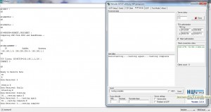 This code first initializes the Software Serial connections to transmit data to WiFi Shield and sets the values for the ssid, ind (only for WEP), and key for the particular network. It then uses the default function setWpa to setup a connection to the WPA network and then the WiFi Shield proceeds to obtain an IP address from the network. The IP Address of the server machine (For example: 192.168.1.2) is put into a String variable and a connection is then made to the server running on that IP address and using the port number 100 (depends on configuration). The server can then send data to the client which is printed as it is on the Serial Monitor. A portion of the incoming data (CID of the client and text written at the server) is stored by the program as a String and can be manipulated in any way.
It can be seen in the image that the client is able to connect to a TCP server created using Hercules Utility. The server then sends data to the client which is received with ESC sequences (indicating the start and end of data transmission) and the client then puts the data, without the ESC sequences, into a String and prints it.
TCP Server
This example is used with the library for Dexter Industries’ WiFi Shield to create a TCP server on Port number 100, which lets TCP clients connect to the Shield and reads data that the client sends.
Steps to execute
1. Change the Port number to a value of your choice.
2. Upload the code and library onto the Arduino with the WiFi Shield.
3. After the server has been created, use the IP address (printed on Serial Monitor after connecting to the WiFi network) and Port number (depends on the value fixed in your code) of the server to have a client connect to it.
4. After the connection has been established, you can enter data (characters,digits etc.) in the client and it will be transmitted to the server as it is.
5. The Serial Monitor prints out the data that is received from the Client. This data is put into a String and is available for manipulation within the program code.
Changes in file
In this file (TCPServer.ino) make the following changes before execution:
1. In the setup function change the values of-
- ssid- SSID or Name of the WiFi Network you are connecting to.
- ind- Key Index with value ranging from 1 to 4, used only in WEP network. Depends on your network configurations.
- key- 10 or 26 hexadecimal characters in case of WEP (example- 4A35535535), OR PassPhrase in case of WPA (example- DEXTERINDUSTRIES). Depends on your network configurations.
2. In the loop function-
- Change the value of the Port number in the line tcpserver.server_start(100) according to the Port number of your choice.
- If you use a WEP network or would like to change the way the Shield connects to the network, refer to the setWpa and setWep functions of the library for details on how to do this.
Description
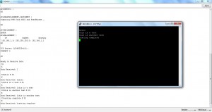 This code first initializes the Software Serial connections to transmit data to WiFi Shield and sets the values for the ssid, ind (only for WEP), and key for the particular network. It then uses the default function setWpa to setup a connection to the WPA network and then the WiFi Shield proceeds to obtain an IP address from the WiFi network. The server is created on port 100 (depends on configuration) using the IP address of the WiFi Shield.
After the server has been created and Serial Monitor prints “Ready to Receive Data” you can connect TCP clients to the Shield via PuTTYtel, Hercules Setup Utility etc. IP address of the server is printed in the Serial Monitor after successful connection to the WiFi network. After a client connects to the server, using the IP address and Port number, you can enter data (characters,digits etc.) in the client window and it will be transmitted to the server and printed on the Serial Monitor. The returned String is devoid of the ESC sequences and only stores the CID of the Client connected to the server (1 character) followed by the data received from that client. A maximum of 15 Clients can be connected to this Server at any given moment.
It can be seen from the image that a client created using PuTTYtel sends the data to the server which is read with ESC sequences, indicating the start and end of data transmission, and then stored and printed without the ESC sequences.
Echo Server
This example is used with the library for Dexter Industries’ WiFi Shield to create a server on port 100 that sends back the data it receives from a client.
Steps to execute
1. Change the Port number to a value of your choice.
2. Upload the code and library onto the Arduino with WiFi Shield and open the Serial Monitor to restart the program to create a server.
3. After the server has been created, use the IP address (printed on Serial Monitor after connecting to the WiFi network) and Port number (depends on the value fixed in your code) of the server and connect a client to it.
4. After the connection has been established, you can enter data (characters,digits etc.) in the client and it will be transmitted to the server as it is.
5. The Serial Monitor prints out the data that is received from the client. This data is put into a String and is available for manipulation within the program code and is sent back to the client.
Changes in file
In this file (EchoServer.ino) make the following changes before execution:
1. In the setup function change the values of-
- ssid- SSID or Name of the WiFi Network you are connecting to.
- ind- Key Index with value ranging from 1 to 4, used only in WEP network. Depends on your network configurations.
- key- 10 or 26 hexadecimal characters in case of WEP (example- 4A35535535), OR PassPhrase in case of WPA (example- DEXTERINDUSTRIES). Depends on your network configurations.
2. In the loop function-
- Change the value of Port number in the line echoserver.server_start(100) according to the Port number of your choice.
- If you use a WEP network or would like to change the way the Shield connects to the network, refer to the setWpa and setWep functions of the library for details on how to do this.
Changes in Arduino
Before executing this code, go to the directory wherever you have installed the Arduino 1.0.1 files and do this (RECOMMENDED, NOT COMPULSORY):
1. In folder arduino-1.0.1hardwarearduinocoresarduino
- Go to file HardwareSerial.cpp
- Find the lines-
#if (RAMEND < 1000)
#define SERIAL_BUFFER_SIZE 16
#else
#define SERIAL_BUFFER_SIZE 64
#endif
and change them to-
#if (RAMEND < 1000)
#define SERIAL_BUFFER_SIZE 16
#else
#define SERIAL_BUFFER_SIZE 128
#endif
2. In folder arduino-1.0.1librariesSoftwareSerial
- Go to file SoftwareSerial.h
- Find the line-
#define _SS_MAX_RX_BUFF 64 // RX buffer size
and change it to-
#define _SS_MAX_RX_BUFF 128 // RX buffer size
This will change the size of the Hardware and Software Serial buffers to 128 and ensure that no data is lost in transmission while the server is sending/receiving data to/from client. If the incoming data is greater than 128 characters long, the buffer in the library will only store the last 128 characters received.
Description
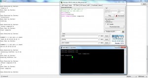 This code first initializes the Software Serial connections to transmit data to WiFi Shield and sets the values for the ssid, ind (only for WEP), and key for the particular network. It then uses the default function setWpa to setup a connection to the WPA network and then the WiFi Shield proceeds to obtain an IP address from the network. A TCP server is then created on port 100 (depends on configuration). When a client, created using PuTTYtel, or Hercules Setup Utility etc., connects to the WiFi Shield, and sends some data, the server reads the data into a string, adds a linefeed (n) to the end of the string and sends the data back to the client. The code runs indefinitely till the shield has a connection to the WiFi network. A maximum of 15 Clients can be connected to this Server at any given moment.
It can be seen from the image that the Server is able to handle more than one client at a time. In the client created using Hercules Utility, the magenta colored characters represent the data sent from the client, and the black colored characters represent the data sent by the server to the client. In both the clients, Hercules Utility and PuTTYtel, the data received from the server has a new line at the end of the data string. The sample output of the code, displayed in the Serial Monitor, can be seen here.
Cosm Client
This example is used with the library for Dexter Industries WiFi Shield to create a client for Cosm/Pachube (www.cosm.com) on the Shield.
Steps to execute
1. Change the values of the FEED ID, API KEY and USER AGENT according to your feed.
2. Upload the code and library onto the Arduino with WiFi Shield and open the Serial Monitor to restart the program which will create a client on the shield.
3. Every time you run the code the value of the analog pin 1 of Arduino is added to the Cosm Feed mentioned in the code.
Request to api.cosm.com
PUT /v2/feeds/<FEED ID>.csv HTTP/1.1rnHost: api.cosm.comrnX-ApiKey: <API KEY>rnUser-Agent: <USER AGENT>rnContent-Length: <Length of data>rnContent-Type: text/csvrnConnection: closernrnSensor1,<value of Analog pin>rn
Where Sensor1,<value of Analog pin> is the main data whose value is to be put on the feed. Sensor1 is the name of the graph (Data stream) to be plotted in the feed. rn is used to separate the PUT method and other parameters of the request header and rnrn is used to indicate end of request header and beginning of data.
Changes in file
In this file (CosmClient.ino) make the following changes before execution:
1. In the setup function change the values of-
- ssid- SSID or Name of the WiFi Network you are connecting to.
- ind- Key Index with value ranging from 1 to 4, used only in WEP network. Depends on your network configurations.
- key- 10 or 26 hexadecimal characters in case of WEP (example- 4A35535535), OR PassPhrase in case of WPA (example- DEXTERINDUSTRIES). Depends on your network configurations.
2. In the loop function-
- Change the value of FEED ID, API KEY, and USER AGENT according to the values of your own feed. OR
If you do not have an account on cosm.com and would not like to create one, do not make any changes to the FEED ID, API KEY or USER AGENT values set in this example.
The following values are used in the code-
Project ID/FEED ID: 82525
API KEY: 4c9QGeVwNDTmjTZLRoYhGsWOA8mSAKxSU2UrYnRMTyszST0g
Project Name/USER AGENT: Cosm Arduino Example (82525)
To see the previous or current values for this feed go to: www.cosm.com/feeds/82525 - Change the value of the pin, the reading of which you want to post on the Cosm feed.
- If you use a WEP network or would like to change the way the Shield connects to the network, refer to the setWpa and setWep functions of the library for details on how to do this.
How to create your own feed
1. Create an account on www.cosm.com
2. Click on the button ‘Device/Feed’.
3. Select ‘Arduino’.
4. Give a title to your feed and Click ‘Next’.
5. Add tags for your feed (optional) and Click ‘Next’.
6. Click ‘Create’.
7. From the program automatically generated, use the lines defined immediately after the header files to get the values of API KEY, FEED ID, and USER AGENT.
Example:
#define APIKEY “4c9QGeVwNDTmjTZLRoYhGsWOA8mSAKxSU2UrYnRMTyszST0g”
#define FEEDID 82525 // your feed ID
#define USERAGENT “Cosm Arduino Example (82525)” // user agent is the project name
Copy these values and insert them at the relevant locations in this example.
8. You can now observe the pin value on your feed every time you successfully run the program.
Changes in Arduino
Before executing this code, go to the directory wherever you have installed the Arduino 1.0.1 files and do this:
1. In folder arduino-1.0.1hardwarearduinocoresarduino
- Go to file HardwareSerial.cpp
- Find the lines-
#if (RAMEND < 1000)
#define SERIAL_BUFFER_SIZE 16
#else
#define SERIAL_BUFFER_SIZE 64
#endif
and change it to-
#if (RAMEND < 1000)
#define SERIAL_BUFFER_SIZE 16
#else
#define SERIAL_BUFFER_SIZE 128
#endif
2. In folder arduino-1.0.1librariesSoftwareSerial
- Go to file SoftwareSerial.h
- Find the line-
#define _SS_MAX_RX_BUFF 64 // RX buffer size
and change it to-
#define _SS_MAX_RX_BUFF 128 // RX buffer size
This will change the size of the Hardware and Software Serial buffers to 128 and ensure that no data is lost in transmission while the client is sending/receiving to/from Cosm server. The buffer in the library will only store the last 128 characters received.
Description
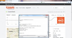 This code first initializes the Software Serial connections to transmit data to WiFi Shield and sets the values for the ssid, ind (only for WEP), and key for the particular network. It then uses the default function setWpa to setup a connection to the WPA network and then WiFi Shield proceeds to obtain an IP address from the network. A client is then created which connects to port 80 of the cosm.com server by using the hostname ‘api.cosm.com’ and finding its IP address through DNS lookup. Analog value of pin 1 is then read and put into the PUT HTTP request along with the Feed ID, Api Key, and User Agent.
It can be seen in the image that the analog pin value which the PUT request sent to cosm.com feed, is displayed immediately on the link of the feed.
Twitter Client
This example is used with the library for Dexter Industries’ WiFi Shield to read information of a particular Twitter (www.twitter.com) user’s timeline. It reads information about tweets of a user, like- tweet text, source application of the tweet, user information and more.
Steps to execute
1. Change the Twitter handle to the handle of the user whose tweets you wish to see.
2. Upload the code and library to the Arduino with the WiFi Shield.
3. Open the Serial Monitor to restart the program, create the Twitter client and see the data that is received from it.
Request to api.twitter.com
GET /<APIversion>/statuses/user_timeline.json?screen_name=<user’s twitter handle><¶meter=value>&count=<number of tweets you want to see> HTTP/1.1rnrn
Where APIversion has a value 1 (recommended) or 1.1, user’s twitter handle is seen as a string of characters following @ on www.twitter.com and is unique for each user. The parameter ‘count’ specifies the number of tweets of the user that will be returned. For more information on GET method and various other parameters (like trim_user) for twitter user’s timeline visit: GET User Timeline Request. For other methods of REST API version 1, visit: REST API 1 Details. rnrn is used to indicate the end of HTTP request.
To confirm/check output for:
GET /1/statuses/user_timeline.json?screen_name=dexterind&trim_user=true&count=1 HTTP/1.1
In your browser, paste the link:
api.twitter.com/1/statuses/user_timeline.json?screen_name=dexterind&trim_user=true&count=1 HTTP/1.1
OR
Connect to Twitter via Telnet:
- Open cmd.exe, by Right-Clicking and selecting ‘Run as Administrator’.
- Enter the command: telnet api.twitter.com 80
- Paste: GET /1/statuses/user_timeline.json?screen_name=dexterind&trim_user=true&count=1 HTTP/1.1
- Press ‘Enter’ key twice to indicate end of request.
Changes in file
In this file (TwitterClient.ino) make the following changes:
1. In the setup function change the values of-
- ssid- SSID or Name of the WiFi Network you are connecting to.
- ind- Key Index with value ranging from 1 to 4, used only in WEP network. Depends on your network configurations.
- key- 10 or 26 hexadecimal characters in case of WEP (example- 4A35535535), OR PassPhrase in case of WPA (example- DEXTERINDUSTRIES). Depends on your network configurations.
2. In the loop function-
- Change the value of screen_name (default value is “dexterind”), in the request, to the twitter handle of the user whose tweets you would like to see. Change the value of count in the request to the number of tweets you want to see. Add or delete any parameters and their values according to your need.
- If you use a WEP network or would like to change the way the Shield connects to the network, refer to the setWpa and setWep functions of the library for details on how to do this.
Changes in Arduino
Before executing this code, go to the directory wherever you have installed the Arduino 1.0.1 files and do this:
1. In folder arduino-1.0.1hardwarearduinocoresarduino
- Go to file HardwareSerial.cpp
- Find the lines-
#if (RAMEND < 1000)
#define SERIAL_BUFFER_SIZE 16
#else
#define SERIAL_BUFFER_SIZE 64
#endif
and change it to-
#if (RAMEND < 1000)
#define SERIAL_BUFFER_SIZE 16
#else
#define SERIAL_BUFFER_SIZE 128
#endif
2. In folder arduino-1.0.1librariesSoftwareSerial
- Go to file SoftwareSerial.h
- Find the line-
#define _SS_MAX_RX_BUFF 64 // RX buffer size
and change it to-
#define _SS_MAX_RX_BUFF 128 // RX buffer size
This will change the size of the Hardware and Software Serial buffers to 128 and ensure that no data is lost in transmission while the client is sending/receiving data to/from Twitter server. The buffer in the library will only store the last 128 characters received, but will print the incoming bulk data (far greater than 128 characters) very quickly without any loss of data.
Description
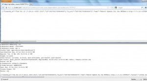 This code first initializes the Software Serial connections to transmit data to WiFi Shield and sets the values for the ssid, ind (only for WEP), and key for the particular network. It then uses the default function setWpa to setup a connection to the WPA network and then the WiFi Shield proceeds to obtain an IP address from the network. A client is then created which connects to port 80 of the twitter.com server by using the hostname ‘api.twitter.com’ and finding its IP address through DNS lookup. The GET HTTP request is then sent to the server and the response is read.
The image shows the response received by the WiFi Shield along with the response HTTP header and the same output in the web browser page (without the response HTTP header). The sample output of the code, displayed in the Serial Monitor, can be seen here.
Web Client
This example is used with the library for Dexter Industries’ WiFi Shield to read the response HTML data from Google (www.google.com) for a particular search query. It reads the page returned for the query.
Steps to execute
1. Change the query terms according to your needs.
2. Upload the code and library to the Arduino with the WiFi Shield.
3. Open the Serial Monitor to restart the program, create the Google Client and see the response data that is received from it.
Request to www.google.com
GET /search?q=<the query terms to search for (separated by +)> HTTP/1.0rnrn
Where rnrn is used to indicate end of request.
To confirm/check output for:
GET /search?q=dexter+industries HTTP/1.0
In your browser, paste the link:
www.google.com/search?q=dexter+industries
OR
Connect to Google via Telnet:
- Open cmd.exe, by Right-Clicking and selecting ‘Run as Administrator’.
- Enter the command: telnet www.google.com 80
- Paste: GET /search?q=dexter+industries HTTP/1.0
- Press ‘Enter’ key twice to indicate end of request.
Changes in file
In this file (WebClient.ino) make the following changes:
1. In the setup function change the values of-
- ssid- SSID or Name of the WiFi Network you are connecting to.
- ind- Key Index with value ranging from 1 to 4, used only in WEP network. Depends on your network configurations.
- key- 10 or 26 hexadecimal characters in case of WEP (example- 4A35535535), OR PassPhrase in case of WPA (example- DEXTERINDUSTRIES). Depends on your network configurations.
2. In the loop function-
- Change the search query terms, in the request, according to your needs.
- If you use a WEP network or would like to change the way the Shield connects to the network, refer to the setWpa and setWep functions of the library for details on how to do this.
Changes in Arduino
Before executing this code, go to the directory wherever you have installed the Arduino 1.0.1 files and do this:
1. In folder arduino-1.0.1hardwarearduinocoresarduino
- Go to file HardwareSerial.cpp
- Find the lines-
#if (RAMEND < 1000)
#define SERIAL_BUFFER_SIZE 16
#else
#define SERIAL_BUFFER_SIZE 64
#endif
and change it to-
#if (RAMEND < 1000)
#define SERIAL_BUFFER_SIZE 16
#else
#define SERIAL_BUFFER_SIZE 128
#endif
2. In folder arduino-1.0.1librariesSoftwareSerial
- Go to file SoftwareSerial.h
- Find the line-
#define _SS_MAX_RX_BUFF 64 // RX buffer size
and change it to-
#define _SS_MAX_RX_BUFF 128 // RX buffer size
This will change the size of the Hardware and Software Serial buffers to 128 and ensure that no data is lost in transmission while the client is sending/receiving data to/from Google Server. The buffer in the library will only store the last 128 characters received, but will print the incoming bulk data (far greater than 128 characters) very quickly without any loss of data.
Description
This code first initializes the Software Serial connections to transmit data to WiFi Shield and sets the values for the ssid, ind (only for WEP), and key for the particular network. It then uses the default function setWpa to setup a connection to the WPA network and then the WiFi Shield proceeds to obtain an IP address from the network. A Web client is then created which connects to port 80 of the Google server by using the hostname ‘www.google.com’ and obtaining an IP Address for it through DNS lookup. The GET HTTP request is then sent to the google server and a response is read.
Web Client 2
This example is used with the library for Dexter Industries’ WiFi Shield to read information from “latest.txt” on Arduino Homepage.
Steps to execute
1. Upload the code and library to the Arduino with the WiFi Shield.
2. Open the Serial Monitor to restart the program, create the client to the Arduino Homepage and see the response data that is received from it.
Request to www.arduino.cc
GET /latest.txt HTTP/1.1rnHost: www.arduino.ccrnrn
Where rn is used to separate the GET method and Host request header, and rnrn is used to indicate the end of request header.
To confirm/check output for:
GET /latest.txt HTTP/1.1rnHost: www.arduino.cc
In your browser, enter:
www.arduino.cc/latest.txt
OR
Connect to Arduino via Telnet:
- Open cmd.exe, by Right-Clicking and selecting ‘Run as Administrator’.
- Enter the command: telnet www.arduino.cc 80
- Paste: GET /latest.txt HTTP/1.1
- Press ‘Enter’ key once.
- Paste: Host: www.arduino.cc
- Press ‘Enter’ key twice to indicate end of request.
Changes in file
In this file (WebClient2.ino) make the following changes:
1. In the setup function change the values of-
- ssid- SSID or Name of the WiFi Network you are connecting to.
- ind- Key Index with value ranging from 1 to 4, used only in WEP network. Depends on your network configurations.
- key- 10 or 26 hexadecimal characters in case of WEP (example- 4A35535535), OR PassPhrase in case of WPA (example- DEXTERINDUSTRIES). Depends on your network configurations.
2. In the loop function-
- If you use a WEP network or would like to change the way the Shield connects to the network, refer to the setWpa and setWep functions of the library for details on how to do this.
Changes in Arduino
Before executing this code, go to the directory wherever you have installed the Arduino 1.0.1 files and do this:
1. In folder arduino-1.0.1hardwarearduinocoresarduino
- Go to file HardwareSerial.cpp
- Find the lines-
#if (RAMEND < 1000)
#define SERIAL_BUFFER_SIZE 16
#else
#define SERIAL_BUFFER_SIZE 64
#endif
and change it to-
#if (RAMEND < 1000)
#define SERIAL_BUFFER_SIZE 16
#else
#define SERIAL_BUFFER_SIZE 128
#endif
2. In folder arduino-1.0.1librariesSoftwareSerial
- Go to file SoftwareSerial.h
- Find the line-
#define _SS_MAX_RX_BUFF 64 // RX buffer size
and change it to-
#define _SS_MAX_RX_BUFF 128 // RX buffer size
This will change the size of the Hardware and Software Serial buffers to 128 and ensure that no data is lost in transmission while the Client is sending/receiving data to/from Arduino Server. The buffer in the library will only store the last 128 characters received, but will print the incoming data (greater than 128 characters) very quickly without any loss of data.
Description
This code first initializes the Software Serial connections to transmit data to WiFi Shield and sets the values for the ssid, ind (only for WEP), and key for the particular network. It then uses the default function setWpa to setup a connection to the WPA network and then the WiFi Shield proceeds to obtain an IP address from the network. A client is then created which connects to port 80 of Arduino server, obtaining the IP Address of the hostname ‘www.arduino.cc’ through DNS lookup. The GET HTTP request is then issued to the Arduino server and the response is read.
Web Server
This example is used with the library for Dexter Industries’ WiFi Shield to create a simple Web Server. When a client connects to the Shield, and issues a request, the web server shows the value of the first 3 analog input pins.
Steps to execute
1. Change the value of the number of analog pins, and the refresh interval (default value of 7) for browser page.
2. Upload the code and library onto the Arduino with WiFi Shield.
3. Open the Serial Monitor to restart the program and create a server.
4. Create a client, or open the web browser of another machine on the WiFi network and have it connect to the IP address of the server created in step 3.
4. Send a GET request from client or web browser to the server and observe the response.
Request received by server
<anything>rnrn
Where rnrn is used to indicate end of request. rn is similar to pressing the Enter key on keyboard once.
Example: GET / HTTP/1.1rnrn
To see output in a browser
1. Click on the browser of your choice (Mozilla Firefox, Google Chrome, Internet Explorer etc.).
2. Execute the code and observe the output displayed in Serial Monitor.
3. When the Shield acquires an IP address, note down this address.
4. After the server has started, wait 1-2 seconds, enter the IP address obtained in step 3 in the ‘Address bar’ of the Browser and press ‘Enter’ key.
5. You will observe in the browser that the value of the pins is displayed. But this value is retained only till the page is refreshed. After 7 seconds, the page is automatically refreshed and the browser issues the GET request again and now the new and current values for the analog pins are seen in the browser. This continues indefinitely till the server is closed.
Changes in file
In this file (WebServer.ino) make the following changes:
1. In the setup function change the values of-
- ssid- SSID or Name of the WiFi Network you are connecting to.
- ind- Key Index with value ranging from 1 to 4, used only in WEP network. Depends on your network configurations.
- key- 10 or 26 hexadecimal characters in case of WEP (example- 4A35535535), OR PassPhrase in case of WPA (example- DEXTERINDUSTRIES). Depends on your network configurations.
2. In the loop function-
- Change the number of pins you want to print and change the refresh interval from 7 seconds to any value, according to your needs.
- If you use a WEP network or would like to change the way the Shield connects to the network, refer to the setWpa and setWep functions of the library for details on how to do this.
Changes in Arduino
Before executing this code, go to the directory wherever you have installed the Arduino 1.0.1 files and do this:
1. In folder arduino-1.0.1hardwarearduinocoresarduino
- Go to file HardwareSerial.cpp
- Find the lines-
#if (RAMEND < 1000)
#define SERIAL_BUFFER_SIZE 16
#else
#define SERIAL_BUFFER_SIZE 64
#endif
and change it to-
#if (RAMEND < 1000)
#define SERIAL_BUFFER_SIZE 16
#else
#define SERIAL_BUFFER_SIZE 128
#endif
2. In folder arduino-1.0.1librariesSoftwareSerial
- Go to file SoftwareSerial.h
- Find the line-
#define _SS_MAX_RX_BUFF 64 // RX buffer size
and change it to-
#define _SS_MAX_RX_BUFF 128 // RX buffer size
3. In library ‘.h’ file-
- Find the line-
char buffer[128];
and change it to-
char buffer[448];
This will change the size of the Hardware and Software Serial buffers to 128 and ensure that no data is lost in transmission while the Server is sending/receiving data to/from client or browser. The size of the library buffer is changed to 448 to ensure that the complete request header from a browser can be stored.
Description
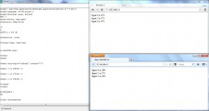 This code first initializes the Software Serial connections to transmit data to WiFi Shield and sets the values for the ssid, ind (only for WEP), and key for the particular network. It then uses the default function setWpa to setup a connection to the WPA network and then the WiFi Shield proceeds to obtain an IP address from the network. A server is then created on port 80. When a client connects to the server and issues a request, the server reads the Client Identifier (CID) of the client from the request and sends the analog values for the first 3 (depends on the code) pins to that client and then closes the connection. If the client is a browser, the server will refresh the browser page after every 7 seconds and the browser will send the GET request to the server at every refresh. It is possible to use several browsers or clients together. A maximum of 15 clients can be connected to this server at a time. It is also possible to issue a request from a TCP client created using PuTTYtel, Hercules Setup Utility etc.
In the figure, the Google Chrome browser, connects to the server first and represents values received several seconds ago. The Mozilla Firefox browser connects later and shows the current values of the pins which can also be seen on the Serial Monitor on the left hand side. The sample output of the code, displayed in the Serial Monitor, can be seen here.
Variables in the library
ssid: Public variable of type String. This is used to define the SSID of the WEP/WPA network of the user.
ind: Public variable of type String. This is used to define the Key Index value used only in WEP networks. Possible values of this variable range from 1 to 4 and are dependent on the network of the user.
key: Public variable of type String. This is used to define the 10 or 26 character hexadecimal key for WEP networks OR the Pass Phrase for WPA networks depending on the network of the user.
buffer: Public variable of type char array. This is used to store the incoming data from the WiFi Shield.
commandStr: Public variable of type String. This is generally used to store and manipulate data and/or commands to be sent to the WiFi Shield.
output: Public variable of type String. This is generally used to store and manipulate the data and/or response received from WiFi Shield.
Macros in the library
checkOK(buff): To check for the String “OK” in a char array ‘buff’ when the response from WiFi Shield is: <CR><LF>OK. Returns true if “OK” found, falseotherwise.
RTS_check(): To check the value of the RTS pin. Returns true if RTS pin in low, falseotherwise.
CTS_start(): To set the output CTS pin to Low, and indicate that the WiFi Shield is Clear to Send data.
CTS_stop(): To set the output CTS pin to High, and indicate that the WiFi Shield is not Clear to Send data.
writech(ch): If the character ch is not Carriage Return (<CR> ; r ; ASCII value 13), Line Feed (<LF> ; n ; ASCII value 10), Space (ASCII value 32) then that character is sent to the WiFi Shield. This is used while sending Gainspan GS1011 Module commands to the WiFi Shield.
Functions in the library
init(): Public function that starts the Software Serial connection at the 9600 baud rate and listens to this connection. It also sets the output mode for the CTS pin and clears the buffer variable. This function is necessary and must be called once from the setup function of the Arduino file. Returns nothing.
Example Call: init();
getstr(): Public function that reads String data from Serial Monitor Box. Can be used to input various commands for the WiFi Shield directly from the text box of the Serial Monitor. Enter a String of characters in the textbox and press ‘Enter’ key. The data is received as <String Command> followed by <CR>, <LF> or <CRLF> which are ignored. Returns the data from the textbox as a String variable.
Example Call: String STR = getstr();
writeStrNoEnd(String): Public function that is used to write partial commands of type String to WiFi Shield. In case a command is too long, it can cause a hangup when transmitted to the WiFi Shield. To avoid sending the complete command all at once, this function can be used to send a portion of it. To indicate the end of a command, the function writeStr must be used after this function. Returns nothing.
Example Preceding Code: String commandStr = “ATE”;
Example Call: writeStrNoEnd(commandStr);
writeStr(String): Public function used to write various commands of type String to WiFi Shield. The function ends the command String with <CR> to indicate that the command has ended. Returns nothing.
Example Call: writeStr(“ATE0”);
writeesc(char, String, char): Public function used in TCP connections to send data of type String to TCP Server and/or Client. It uses the <ESC> character sequences before the start and finish characters to show the start and end of data transmission. For TCP connections start character=’S’ and finish character=’E’. Returns nothing. The character immediately following ‘S’ is the Connection identifier (CID) of the client to which the data is to be sent in the form: <ESC>S<CID><data><ESC>E
Example Call: writeesc(‘S’, “0Dexter Industries”, ‘E’);
Receive(boolean): Public function used to receive serial response data from WiFi Shield which has “OK<CR><LF>” at the end and store it in the buffer char array. This helps in error checking. It must be preceded by a small delay. A Boolean value of true specifies that the function must wait for a response and print it to the Serial Monitor and if no response is found, this function will go into an infinite loop. If a Boolean value of false is specified (default) then the code receives any response (may be garbage) from the WiFi Shield and stores it in the buffer but does not print it. Returns nothing.
Example Preceding Code: delay(10);
Example Call: Receive(true);
readall(): Public function that is used to receive incoming data from WiFi Shield and store it into buffer regardless of the characters in the data. No error checking. Generally used to receive data from TCP Servers and/or Clients. Returns the total number of characters received as an integer value.
Example Call: int chars_received = readall();
clear_read_buffer(): Public function that is used to send a single <CR> character to the WiFi Shield and discards the response (Garbage) received. It also clears the buffer. Returns nothing.
Example Call: clear_read_buffer();
inString(char*, char): Public Inline Function used to find the first position of a character in a char array. Returns the integer position of the character in the char array when it is found. If character is not found, then a value of -1 is returned.
Example Call: int position = inString(“data”,’t’); //returns position=2.
verbose_on(boolean): Public function used to turn Verbose mode of the WiFi Shield ON or OFF. If Boolean value is true (default) the Verbose is turned ON (recommended) and character response will be received from the Shield. If Boolean value is false the Verbose is turned OFF and the response received from the Shield will be integer values. Returns true on successful completion (if ‘OK’ is received), false otherwise.
Example Call: boolean check = verbose_on(true);
echo_on(boolean): Public function used to turn Echo mode of the WiFi Shield ON or OFF. If Boolean value is true the Echo is turned ON and the Shield will echo back the commands that are sent to it. If Boolean value is false (default) Echo will be turned OFF and the Shield will NOT echo back the commands that are sent to it (recommended). Returns true on successful completion (if ‘OK’ is received), false otherwise.
Example Call: boolean check = echo_on(false);
soft_flow_control(boolean): Public function used to enable or disable Software Flow Control of the WiFi Shield. If Boolean value is true Software Flow Control is enabled (recommended) and if the Boolean value is false the Software Flow Control is disabled. Returns true on successful completion (if ‘OK’ is received), false otherwise.
Example Call: boolean check = soft_flow_control(true);
hard_flow_control(boolean): Public function used to enable or disable Hardware Flow Control of the WiFi Shield. If Boolean value is true the Hardware Flow Control is enabled (recommended) and if the Boolean value is false the Hardware Flow Control is disabled. Returns true on successful completion (if ‘OK’ is received), false otherwise.
Example Call: boolean check = hard_flow_control(true);
infra_mode(boolean): Public function used to set the Wireless mode of the WiFi network. If the Boolean value is false then the Infrastructure mode is used and if the value is true the mode is set to Adhoc. Returns true on successful completion (if ‘OK’ is received), false otherwise.
Example Call: boolean check = infra_mode(false);
set_network_config(unsigned int): Public function used to set the Auto Associate Timeout value for the WiFi Shield. The unsigned integer value ranges from 0 to 65535 in 10ms value (Example: 500 = 5 secs). Returns true on successful completion (if ‘OK’ is received), false otherwise.
Example Call: boolean check = set_network_config(1000);
keep_alive(unsigned int): Public function used to set the Keep Alive Timer value for the WiFi Shield. The unsigned integer value ranges from 0 to 65535 in seconds. Returns true on successful completion (if ‘OK’ is received), false otherwise.
Example Call: boolean check = keep_alive(1200);
set_transmit_power(int): Public function used to set the Transmit Power value for the WiFi Shield. The integer value is limited from 0 to 7, where 7 means maximum power. If a value greater than 7 is entered, the value 7 is used. If a value smaller than 0 is entered, the value 0 is used. Returns true on successful completion (if ‘OK’ is received), false otherwise.
Example Call: boolean check = set_transmit_power(7);
disassociate(): Public Inline function that is used to disassociate the current connection of the WiFi Shield with the WiFi network. Returns nothing.
Example Call: disassociate();
wifi_auth_mode(int): Public function used to set the authentication mode being used by the WiFi network. If integer value is 0 then the WiFi Shield connects to a WPA network for which the key used will be the Pass Phrase for the network. If the integer value is 1 then the WiFi network is Open and the value of 2 specifies the authentication mode “Shared with WEP” where the key used will be 10 or 26 hexadecimal character long. Returns true on successful completion (if ‘OK’ is received), false otherwise.
Example Call: boolean check = wifi_auth_mode(0);
DHCP_enable(boolean): Public function used to enable/disable DHCP. If the Boolean value is true then DHCP is enabled and if the WiFi Shield is not connected to a network it will attempt to obtain an IP address from the network when requested. If the Shield is already connected to a network it will try to refresh an existing DHCP address. If the Boolean value is false, the DHCP will be disabled. Returns true on successful completion (if ‘OK’ is received), false otherwise.
Example Call: boolean check = DHCP_enable(true);
associate_with_network(boolean): Public function used to Associate the WiFi Shield with a network. If the Boolean value is false, the Shield attempts to associate with a WiFi network only once and it is possible that it may not be able to associate successfully. If the Boolean value is true the Shield will attempt to associate with the WiFi network continuously, till association is successful. On successful association, the WiFi Shield sends back the IP Address acquired by the Shield, SubNet Mask, and Gateway Address of the network, which can be printed using Receive function. Returns nothing.
Example Call: associate_with_network(true);
setWep(boolean): Public function used as an example to setup a WEP network with the parameters already initialized to some value. If the Boolean value is true then the WiFi authentication mode is set to 2 (Shared with WEP) and if the value is false then the authentication mode is set to 1 (Open). The function also- Turns Echo Off; Enables Software and Hardware Flow Control; Turns Verbose mode On; Sets Wireless mode to Infrastructure; Disassociates from any previous connection with the WiFi network; Sets the Auto Associate Timeout to a value of 1000 (10 secs) and the Keep Alive timer value to 1200 (20 minutes); Sets the Transmit Power to maximum (7); Enables DHCP; Sends the command String- “AT+WWEP<ind>=<key>” to the Shield. In case a user wishes to connect to their own WEP network with different parameter values, it is possible to use this function as an example, to create another function, or simply modify the values in this function. Returns nothing.
Example Call: setWep(true);
setWpa(): Public function used as an example to setup a WPA network with the parameters already initialized to some value. The function turns Echo Off; Enables Software and Hardware Flow Control; Turns Verbose mode On; Sets Wireless mode to Infrastructure; Disassociates from any previous connection with the WiFi network; Sets the Auto Associate Timeout to a value of 1000 (10 secs) and the Keep Alive timer value to 1200 (20 minutes); Sets the Transmit Power to maximum (7); Sets WiFi Authentication mode to 0 (WPA); Enables DHCP; Sends the command String- “AT+WPAPSK=<ssid>,<key>” to the Shield. In case a user wishes to connect to their own WPA network with different parameter values, it is possible to use this function as an example, to create another function or simply modify the values in this function. Returns nothing.
Example Call: setWpa();
dns_lookup(String): Public function used to find the IP address of a hostname. The String value is set to the hostname for which the IP address is to be found. Returns the IP address as a String variable.
Example Call: String DomainIP = dns_lookup(“www.dexterindustries.com”);
server_start(unsigned int): Public function used to start a TCP Server on the Arduino with WiFi Shield. The unsigned integer value ranges from 1 to 65535 and is used to specify the port number on which the server is to be started. The WiFi Shield must be connected to a network and have an IP address before the server can be started. Returns the Connection Identifier (CID) of the server created as an integer value between 0 and 15. As there are only 16 possible CIDs, the server created can have a maximum of only 15 other clients connected to it, at any given instance of time.
Example Call: int TCPServerCID = server_start(100);
client_connect(String, unsigned int): Public function used to connect the WiFi Shield, acting as a TCP client, to an existing server. The String value specifies the IP address of the server, the client is to be connected to. The unsigned integer value is used to specify the port number on which the server is running. The port number can have a value ranging from 1 to 65535. Returns the Connection Identifier (CID) of the Client as an integer value between 0 and 15.
Example Call: int TCPClientCID = client_connect(“192.168.1.2”,100);
tcp_write(String, int): Public function used to send data to a TCP server or client. String has the data that must be sent to the server or client and the integer value is the CID, between 0 and 15, of the client sending the data or the client to which the data is to be sent, respectively. The data is sent in the form: <ESC>S<CID of Client><data><ESC>E. Returns nothing.
Example Call: tcp_write(“Dexter Industries”,2);
tcp_read(): Public function used to receive data from a TCP server or client. This function reads and prints the incoming data from the server or client as it is, with <ESC>S and <ESC>E sequences. Returns the incoming data as a String variable without the <ESC>S and <ESC>E sequences where the first character is the CID of the client and the rest of the string is the actual data.
Example call to function: String tcpData = tcp_read();
cid_disconnect(int): Public Inline function used to disconnect a TCP server or client. The integer value is used to denote the CID (0 to 15) of the server or client which is to be disconnected. Returns true on successful completion (if ‘OK’ is received), false otherwise.
Example Preceding Code: int CID_Server = server_start(2000);
Example Call: boolean check = cid_disconnect(CID_Server);
cid_check(): Public Inline function used to get the details of all the active TCP server and client connections. It prints the CID number, CID type, Protocol, Local port, Remote port, Remote IP address of all the currently running CIDs. Returns nothing.
Example Call: cid_check();
hex2int(char): Public Inline function used to convert a hexadecimal character (usually CID) to an integer value. Returns the integer value of the character (Example: A=10).
Example Call: int value = hex2int(‘A’);


