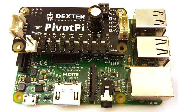
Let’s take a look at the anatomy of a PivotPi servo controller for the Raspberry Pi board.
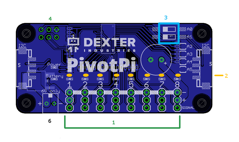
It has the following:
- 8 pin triplets, one for each servo
- 8 LEDs
- A pair of Address switches
- A 6-pin header to connect to the Raspberry Pi.
- Two Grove-style I2C ports at each end
- A Power connector
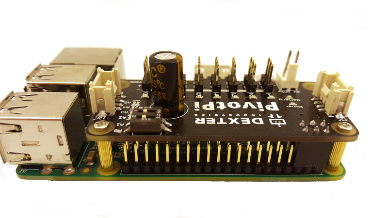
It’s recommended that the toggle switches be in their default position for now as in this photo:
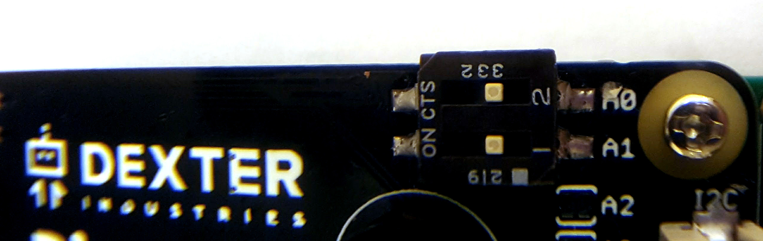
PivotPi Default Address Switches Position
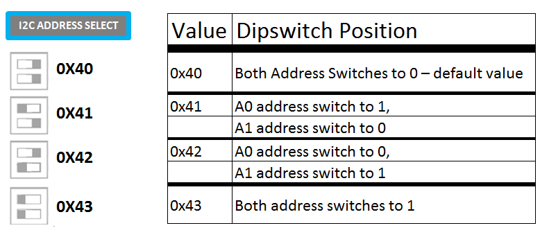
Setting PivotPi Address
As PivotPi boards are using the I2C protocol for communication, you need to give them an address by setting the Address switches to an appropriate position for your specific project. If you are unfamiliar with I2C protocol rest assured that all will work fine if you go with the default position and set both address switches to low.
Here are the possible addresses and corresponding switch positions:
Connecting the Servo Controller for the Raspberry Pi
The PivotPi can be connected in one of two ways: through the header pins directly on the Raspberry Pi, or with a Grove cable to the I2C port.
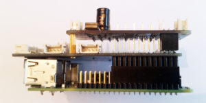
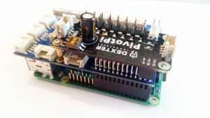
With the Raspberry Pi GPIO Pins
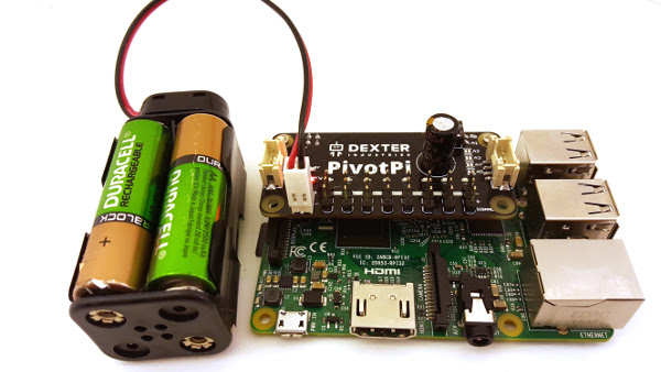
The PivotPi is connected directly to the Raspberry Pi via the Pi GPIO Pins.
The six-pin header connects directly to the pins as shown in the picture. Some posts are supplied to provide some mechanical support and stabilize the PivotPi.
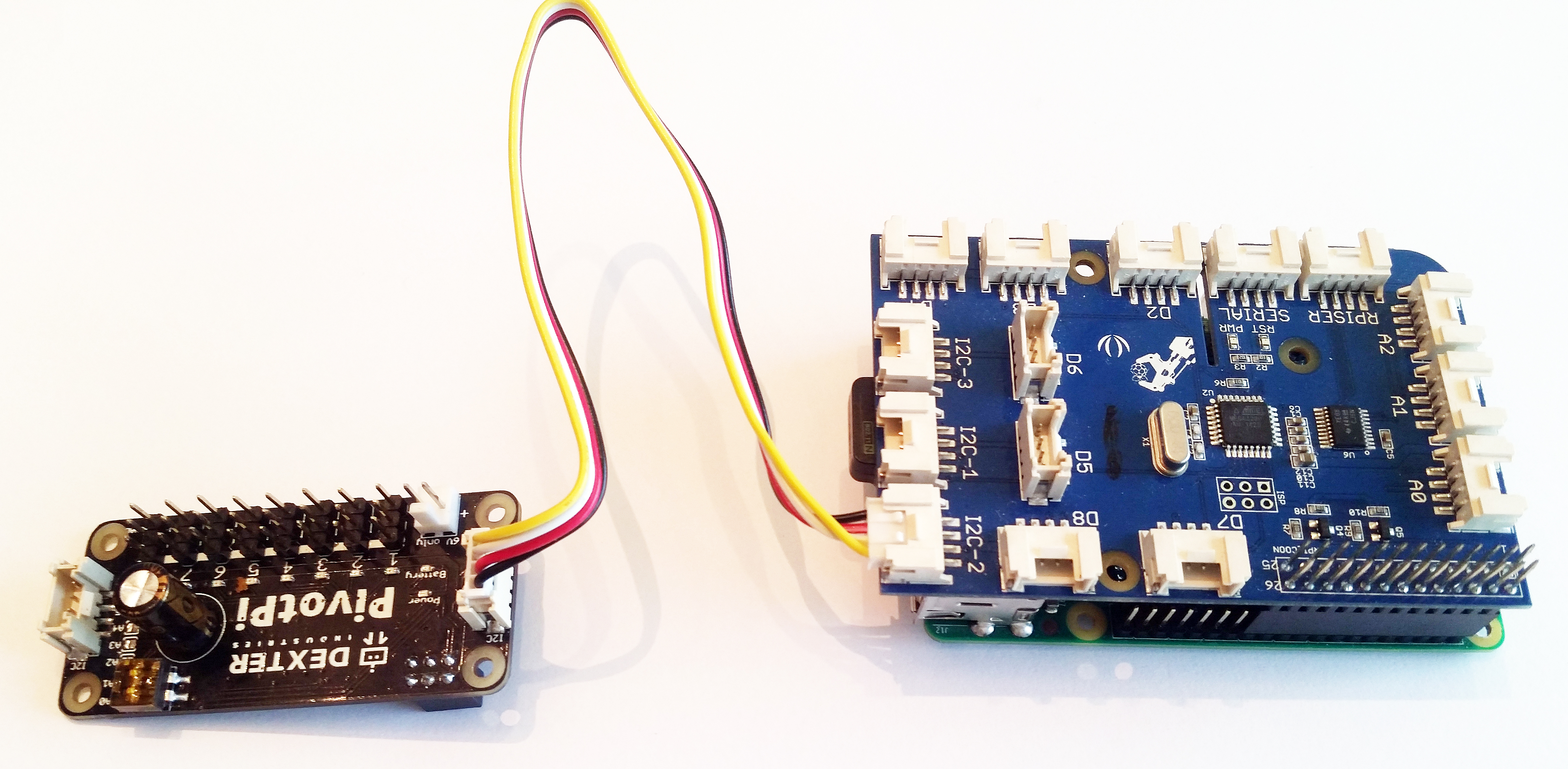
With GoPiGo
The PivotPi needs to be connected via its I2C port to the I2C port on the GoPiGo board. Below is a picture of the GoPiGo and the PivotPi connected via a Grove cable.
With GrovePi
You have two options here:
- You can connect the PivotPi via the I2C port and a Grove cable.

- You can slip the PivotPi onto the GrovePi header and use the supplied posts for mechanical stability.


With another PivotPi
PivotPis can be daisy-chained for big projects that require more than 8 servos. See the multiple PivotPis section for more details
The PivotPi needs its own power source and cannot be powered from the Raspberry Pi or the robot. A 4xAA battery pack comes with each PivotPi. You will need 4 AA batteries to power your PivotPi.
Installing the PivotPi Servos
Here we will show how to attach servos to the servo controller for the Raspberry Pi. When planning your project, you have to take into consideration that each servo must be mounted onto a stable base, securing it in place with tie wraps or screws. A stable base is crucial for proper servo behavior.
Here’s a servo solidly held in place with two tie wraps and double sided tape.
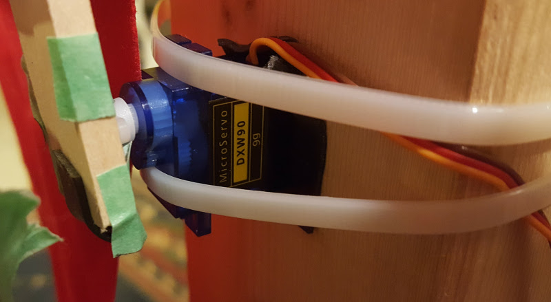
When you’re ready to connect the servo wires to the PivotPi you first need to decide which port you will use. Ports are numbered from 1 to 8 on the board. They are all equivalent. The small servo comes with three wires: brown, red, and orange. The large servo has the following colors: black, red, and white.
The brown and the black go on the inner pin (labelled ‘-‘), the red on the center pin (labelled ‘+’), and either the orange or the white on the outer pin (labelled ‘SIGNAL’). The following video details the process.