
Pivotpi Technical Documentation
PivotPi Technical Documentation
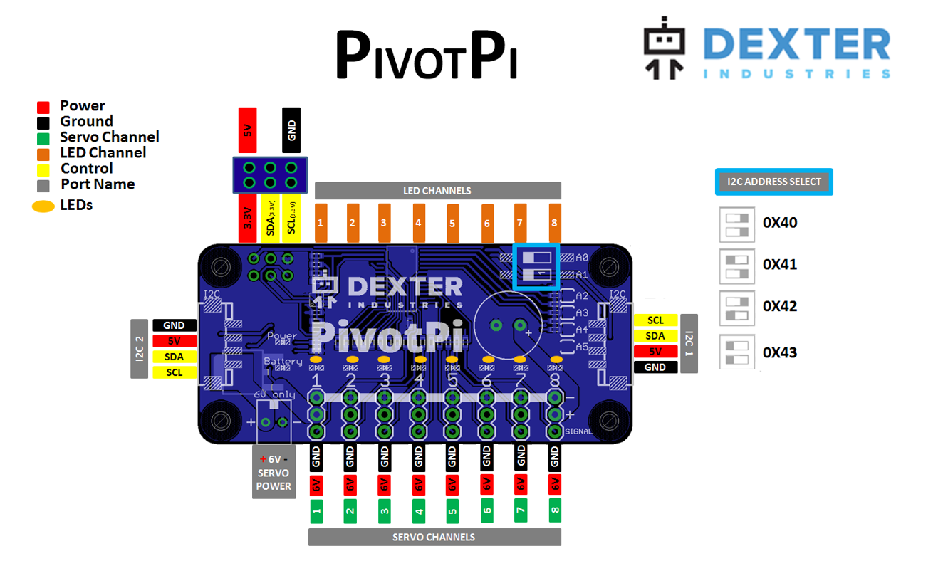
The PivotPi is a servo controller for the Raspberry Pi. It’s based on the PCA9685 I2C PWM controller, and can control up to 8 servos, as well as 8 built-in LEDs.
PivotPi Diagram
Daisy Chain Addressing
PivotPi boards can be daisy chained to support additional servos.
To use multiple PivotPis, using a Grove cable, you can simply plug from one board to another. In order to control each PivotPi independently, it is necessary to assign a unique I2C address to each of them.
With the onboard switches A0 and A1, you can set the address to:
- 0x40 (A0=0 A1=0)
- 0x41 (A0=1 A1=0)
- 0x42 (A0=0 A1=1)
- 0x43 (A0=1 A1=1)
Frequency and Control
The PCA9685 generates 16 channels of 12-bit PWM at a specified frequency. It uses an internal clock to count from 0 through 4095 (0 through ((2^12) – 1)), where it overflows back to 0.
To control the duty cycle, you can specify the “on” and “off” times for each channel. During the count, when it reaches the “on” time, it writes the PWM channel pin high, and when it reaches the “off” time, it writes the PWM channel pin low.
A PWM signal of 1500uS is typically the center position of a servo, and 750-2250uS is roughly the overall range supported. Every servo is different, and some might support 500-2500uS or maybe even a little wider range. Updating servos at 50Hz to 60Hz is nominal.
To control the servos from the PCA9685, the frequency needs to be set to e.g. 60Hz, and the time between the “on” and the “off” times needs to be within the range supported by the servo (750-2250uS should be safe). With a 12-bit PWM running at 60Hz, the difference in raw value between “on” and “off” should be about 185 to 553 (for the range of 750-2250uS). Using the Python drivers for the PivotPi, you can specify either microseconds (most accurate) or degrees (simple, and close enough for most applications), and the drivers will do the calculations.
Power
In order to run, a servo needs both power and a target set using a PWM signal. Servos typically require a 6v power supply (4x 1.5v alkaline AA, or 5x 1.2v NiMH AA), but they will usually run (with reduced torque) on voltages down to 4.5v or so.
LEDs
The LEDs are connected in a common-anode configuration where the PCA9685 drives the cathode (low-side). In this setup, the PWM value and the LED brightness are inversely proportional. A PWM duty cycle of 75% will turn the LED on 25%, and a PWM duty cycle of 10% will turn on the LED at 90%. Using the Python drivers for the PivotPi, you can control the LED brightness level using percentage (0-100).