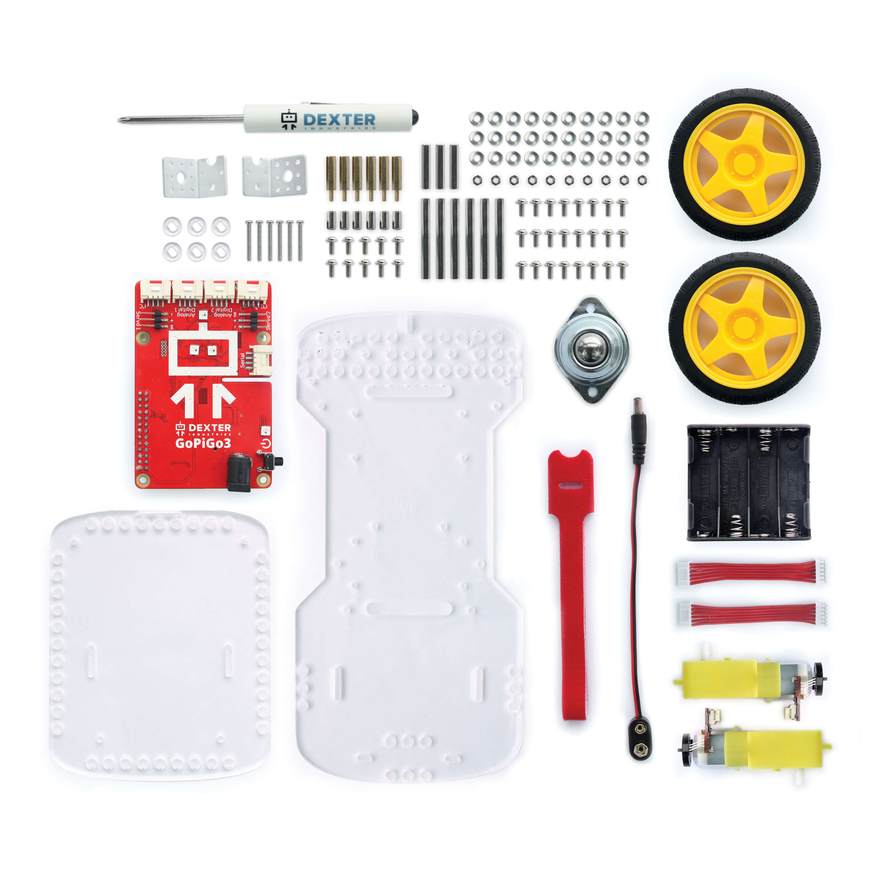
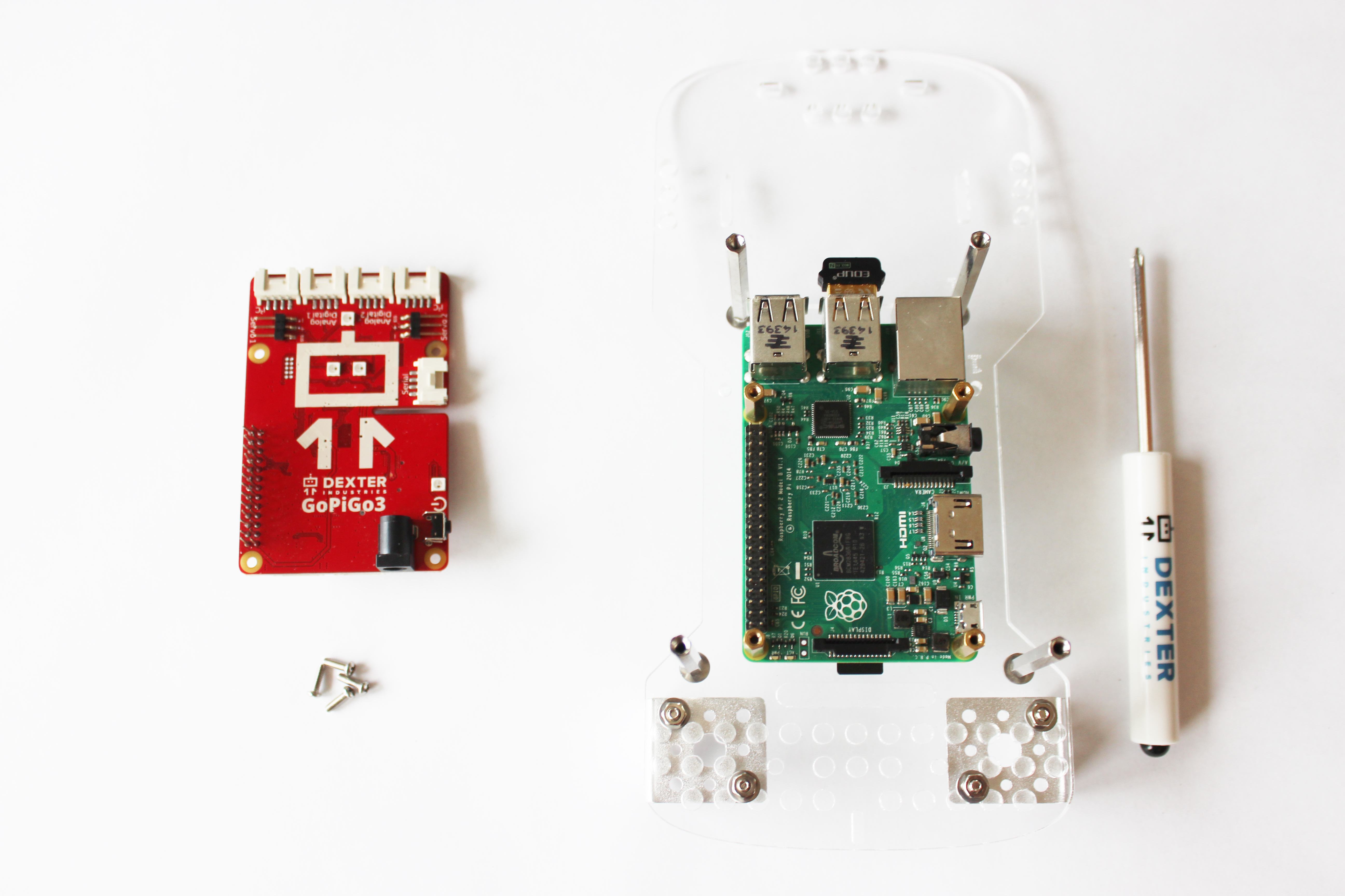
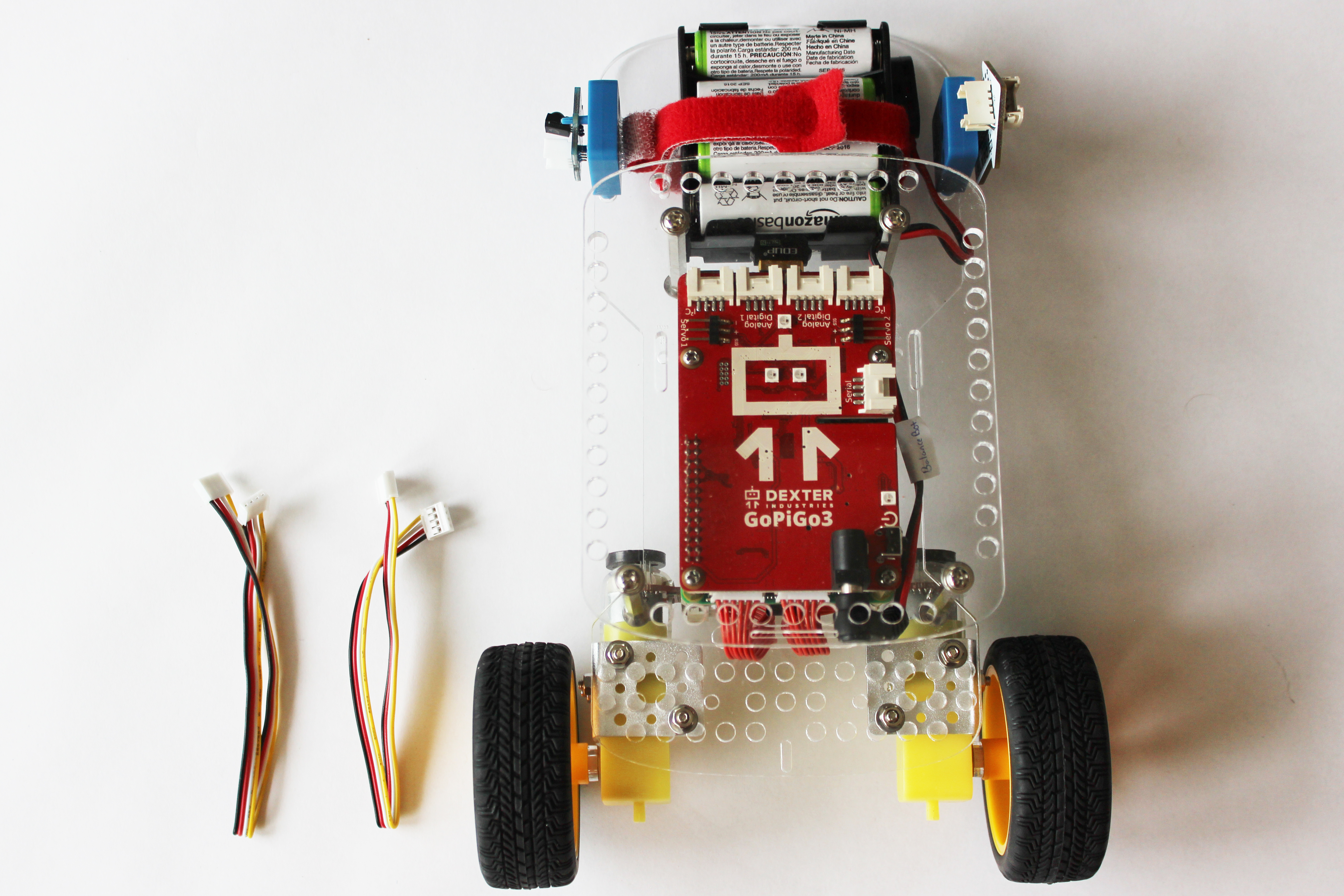
GoPiGo3 Raspberry Pi Robot Kit Components – Click on the image to see a closeup.
These instructions show how to assemble the GoPiGo3 BalanceBot. The GoPiGo3 can be assembled into a balancing robot. If you are looking for instructions to assemble the GoPiGo3 in a car robot configuration click here.
Items You’ll Need to Assemble the GoPiGo3 BalanceBot
- GoPiGo3 Base Kit
- BalanceBot Kit
- Raspberry Pi (green computer board)
- SD Card with Dexter Industries software
- USB Drive (if using DexterOS)
- Dexter Industries Wifi Dongle
- 8 AA Batteries
*BalanceBot Extension Kit available here.
Part 1. Unpack the GoPiGo3 Box
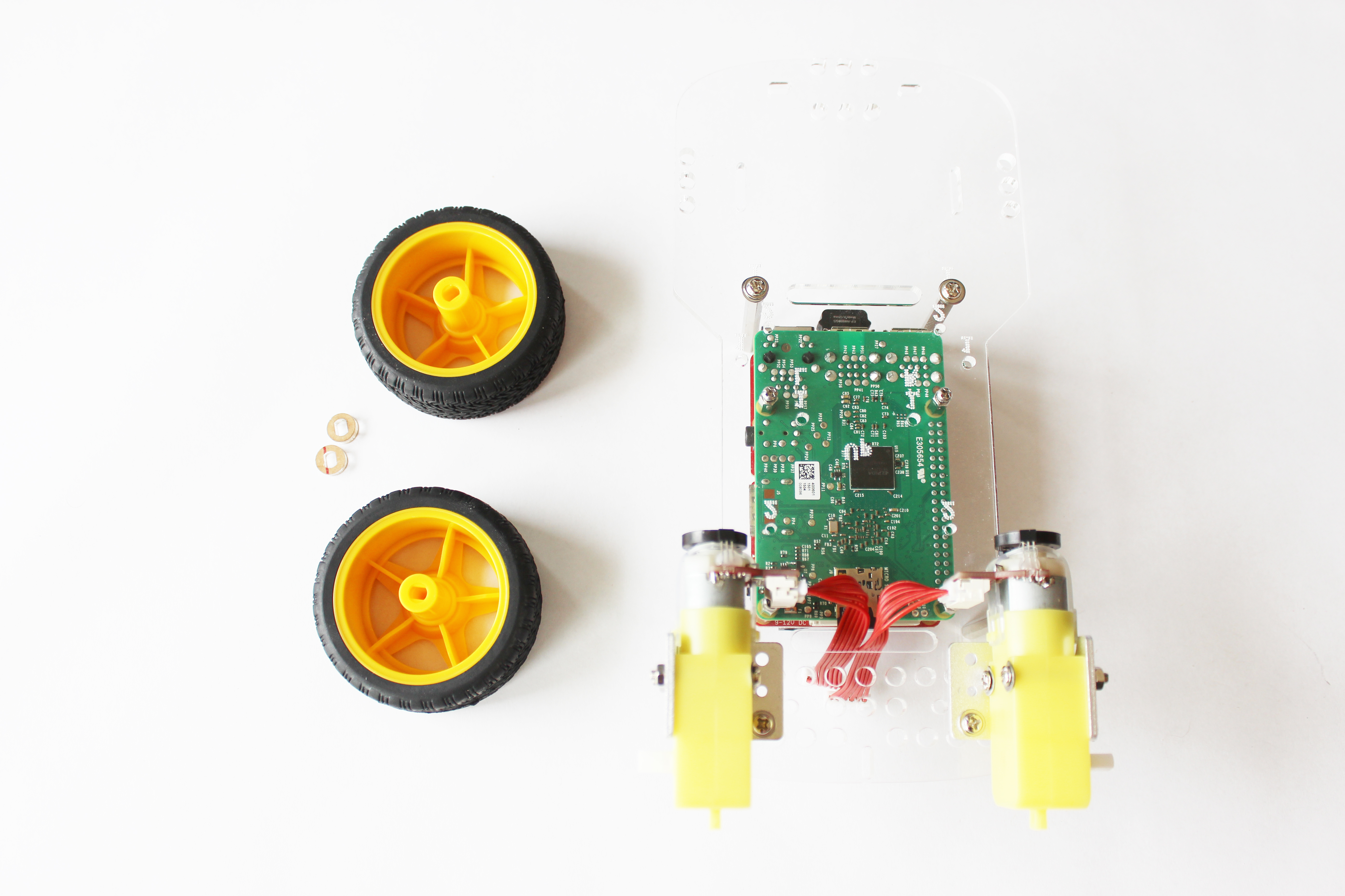
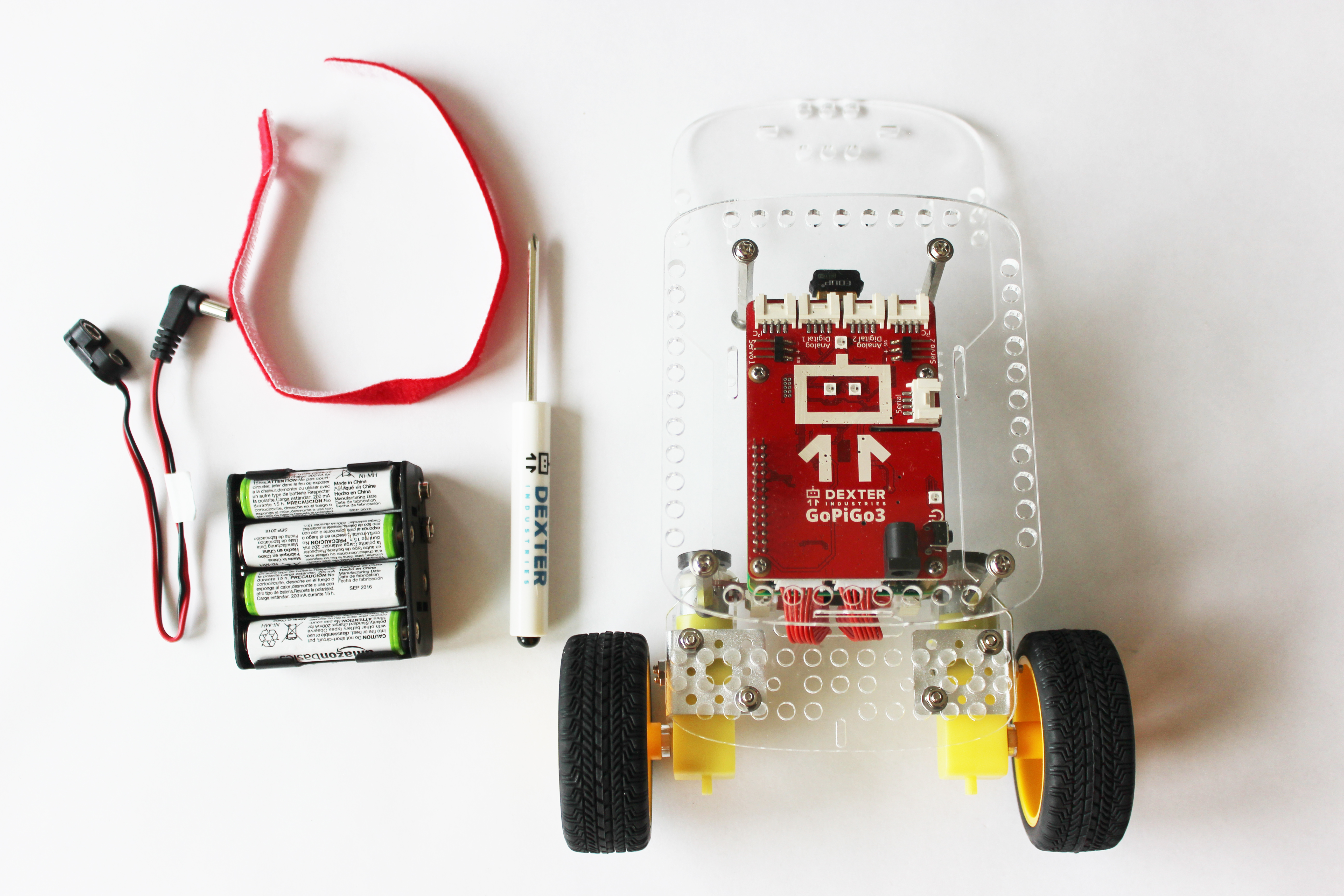
In the GoPiGo3 Base Kit box you should find the following:
- 2 Yellow Wheels
- 2 Motors
- 2 Motor Cables
- GoPiGo3 Board (red)
- 2 Metal Motor Brackets
- 1 Metal Caster Wheel
- 2 Large Acrylic Pieces (body and canopy)
- 1 Battery Box
- 1 Battery Cable
- 1 Velcro Strap
- 1 Small Screwdriver
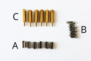
You should have one small bag of hardware that contains:
- (A) 6 Short Silver Posts
- (B) 10 Mini Screws
- (C) 6 Gold Posts
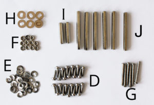
You should have one large bag of hardware that contains:
- (D) 24 Short Screws
- (E) 30 Washers
- (F) 10 Nuts
- (G) 6 Long Screws
- (H) 6 Round Acrylic Spacers
- (I) 3 Medium Silver Posts
- (J) 6 Long Silver Posts
Part 2. Find the Acrylic Parts
The clear acrylic pieces of the GoPiGo3 may come in a protective covering. If yours shipped with this coating, you should be able to peel them off easily. Peel the protective coating away from the 2 large acrylic pieces. You may also want to peel the protective coating from the 2 small round acrylic spacers; they are in the large bag of hardware.
Part 3. Attach the Motor Mounts
What you’ll need:
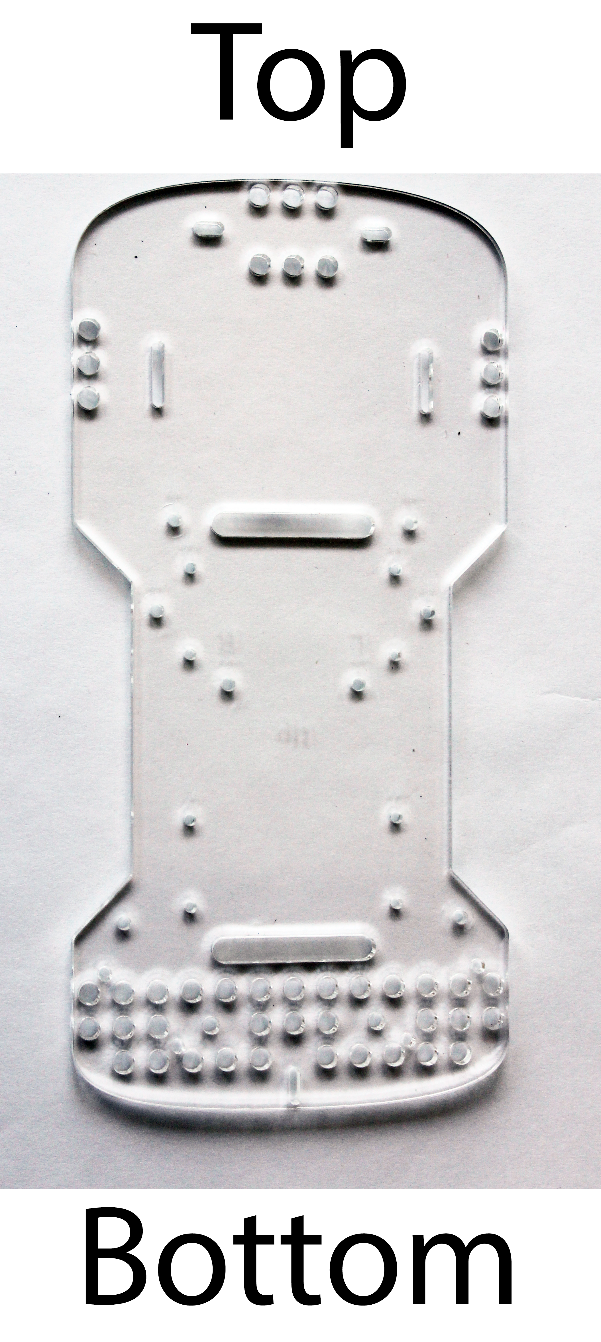
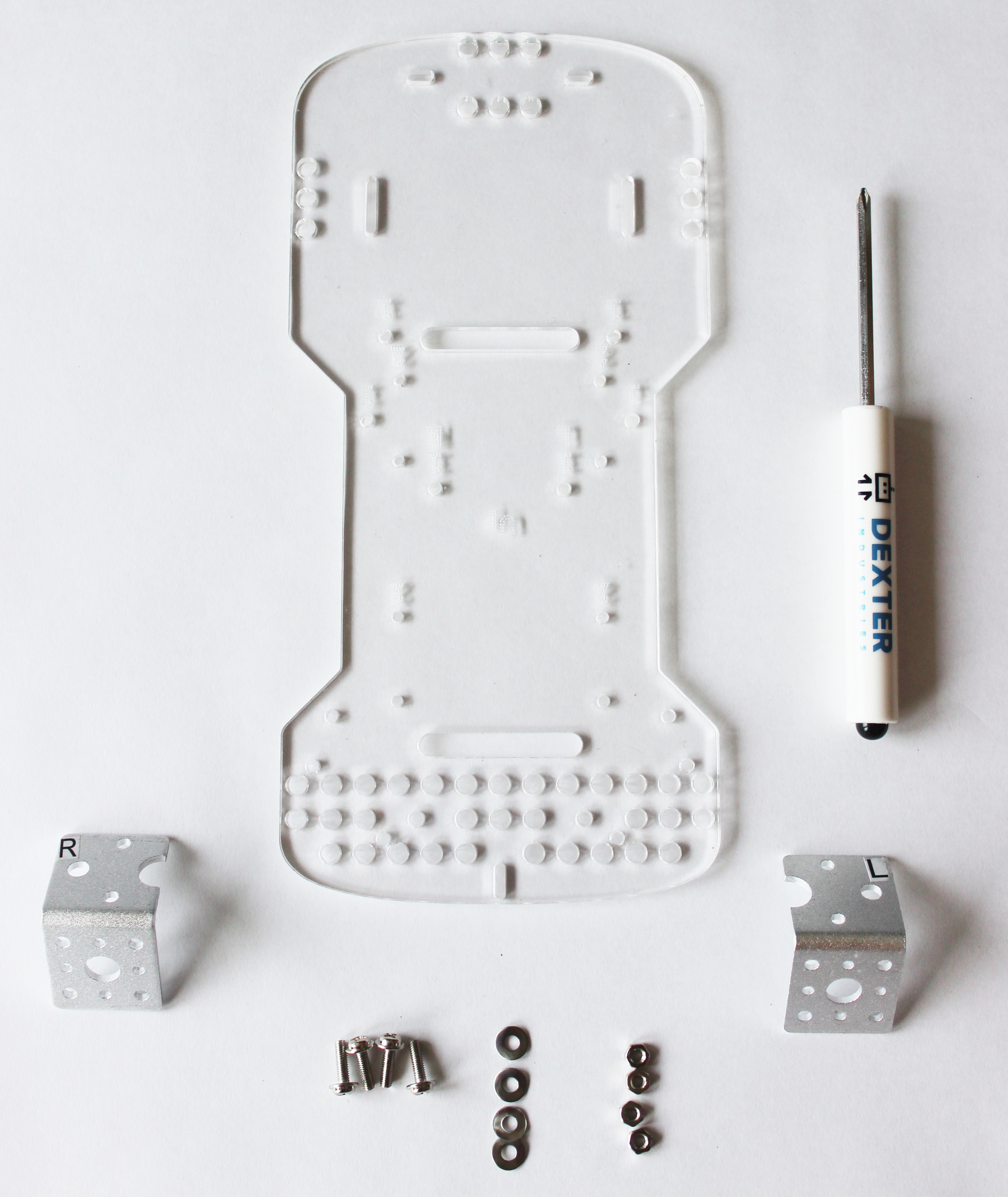
- The GoPiGo3 body – The largest piece of acrylic in your kit.
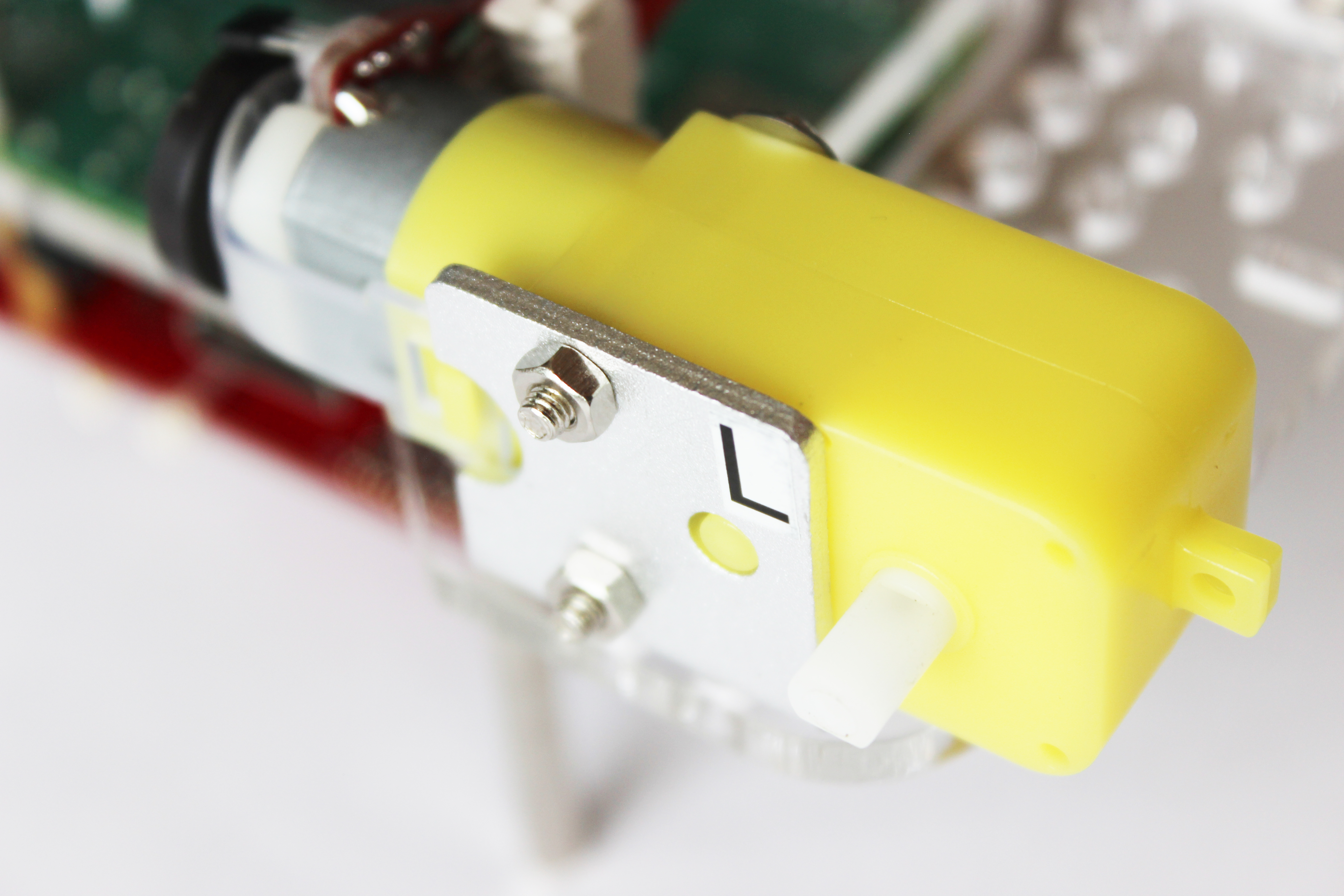
- 2 Metal Motor Brackets – These come labeled with a “L” and “R”, meaning Left and Right.
- Hardware from the large bag – (D) 4 short screws, (E) 4 washers, and (F) 4 nuts.
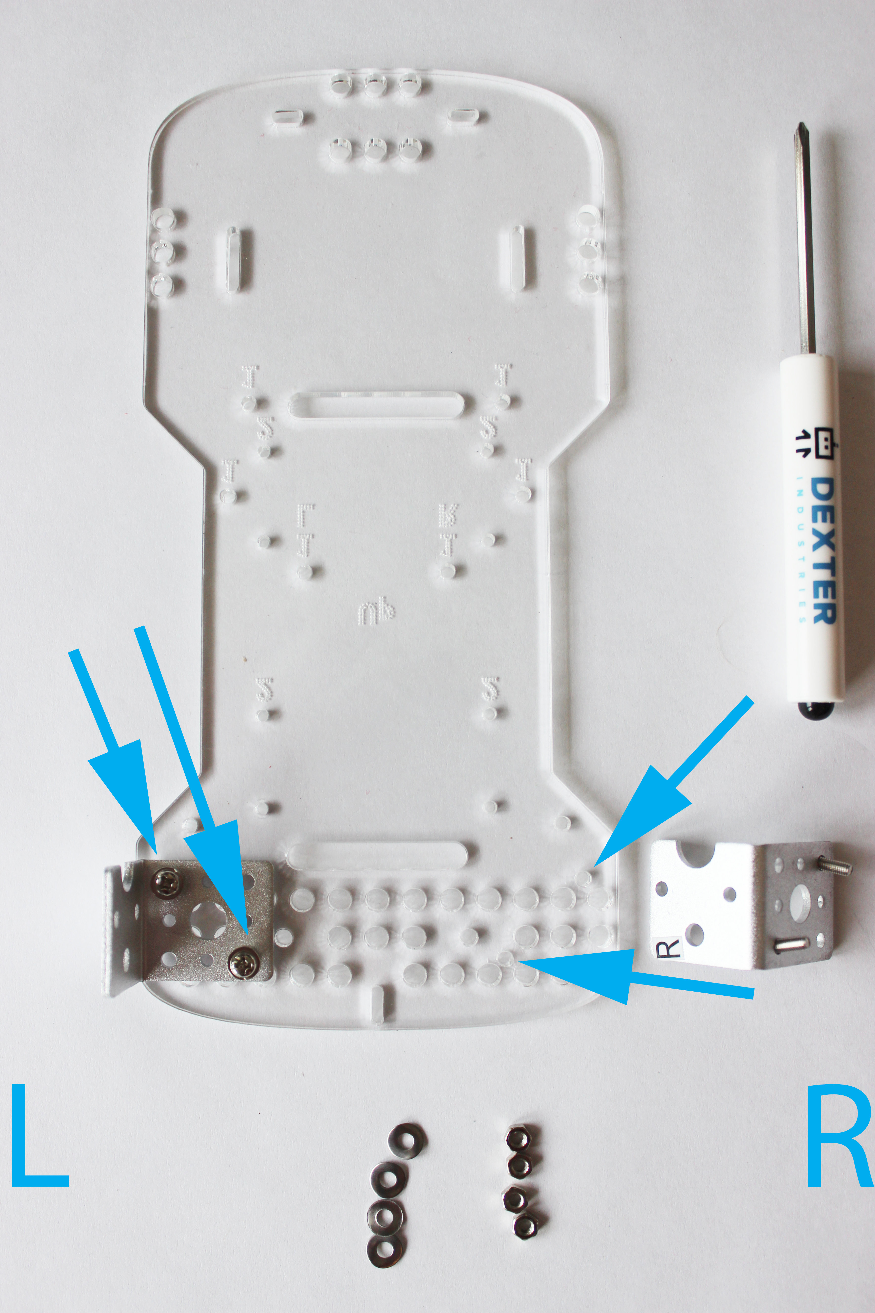
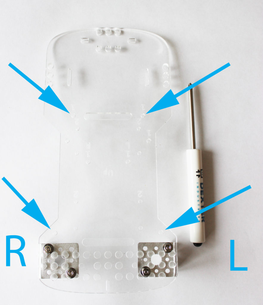
Turn the acrylic upside, with the etching facing down. Next, slide four washers onto the four screws. Slip the screws through the brackets, and into the four mounting holes for the BalanceBot configuration.
The mounting holes for the BalanceBot configuration are shown below.
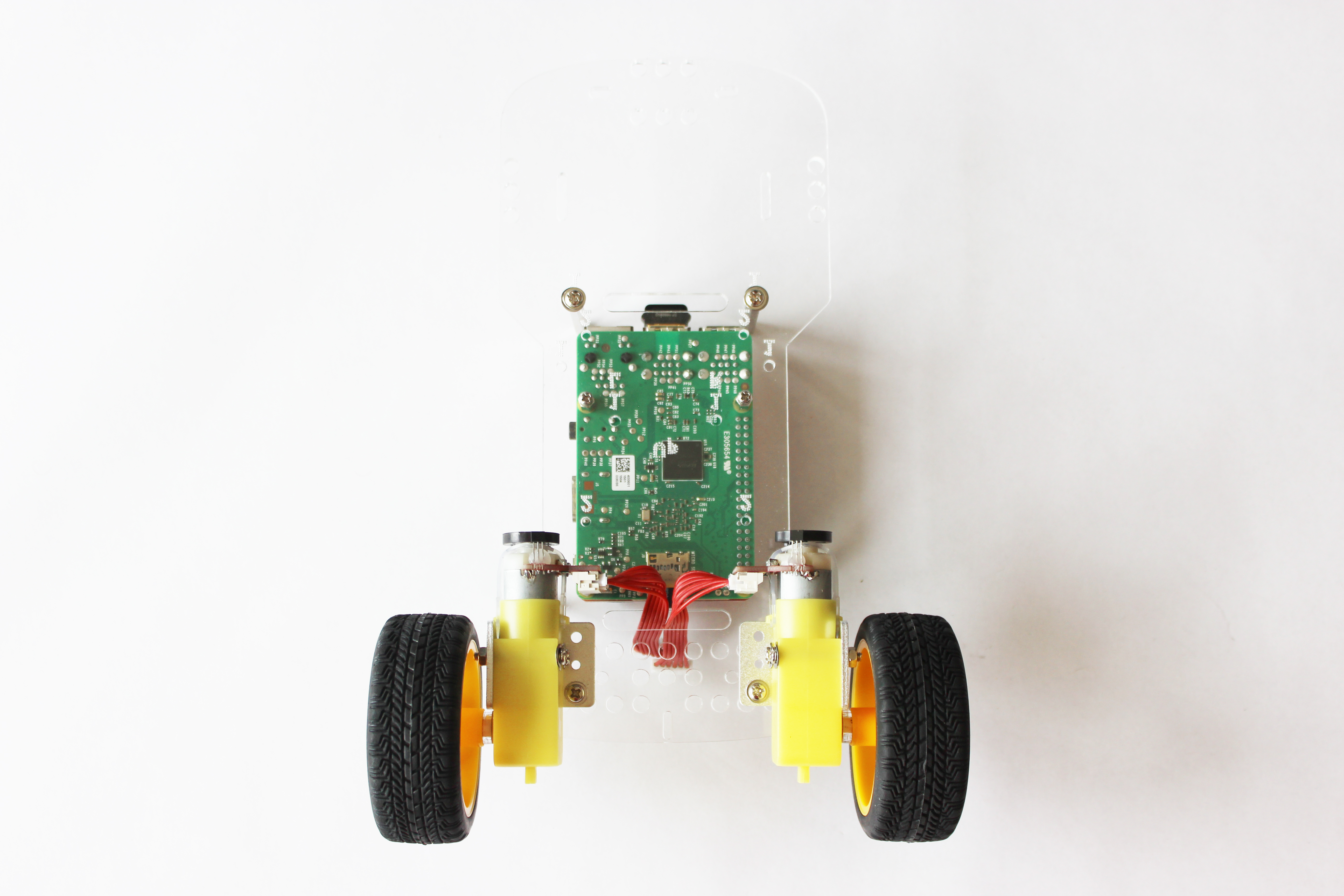
Detailed view of the brackets attached, as viewed from the front of the GoPiGo3 BalanceBot. The half-moon cuts in the brackets should be pointing upwards, towards the top of the BalanceBot.
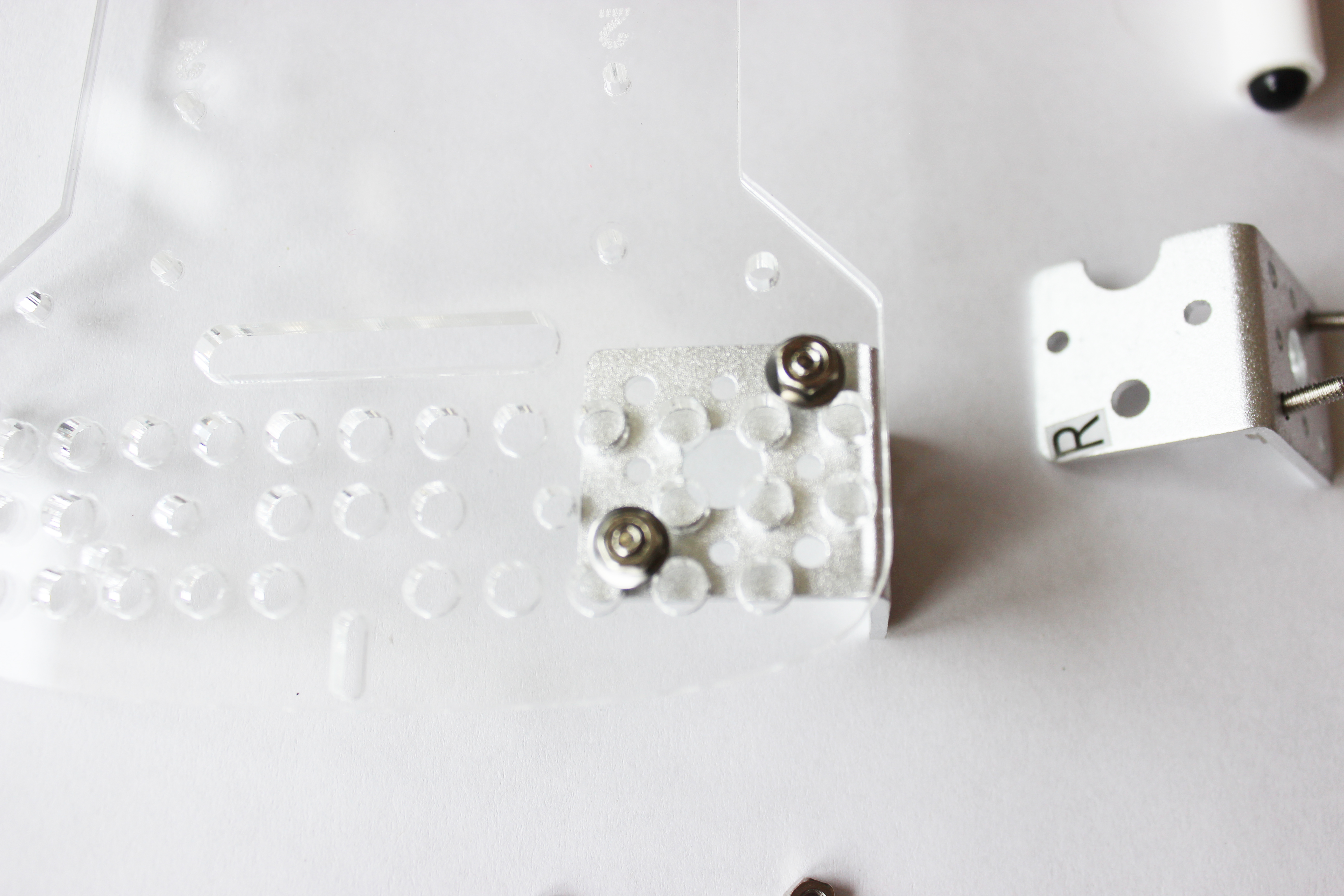
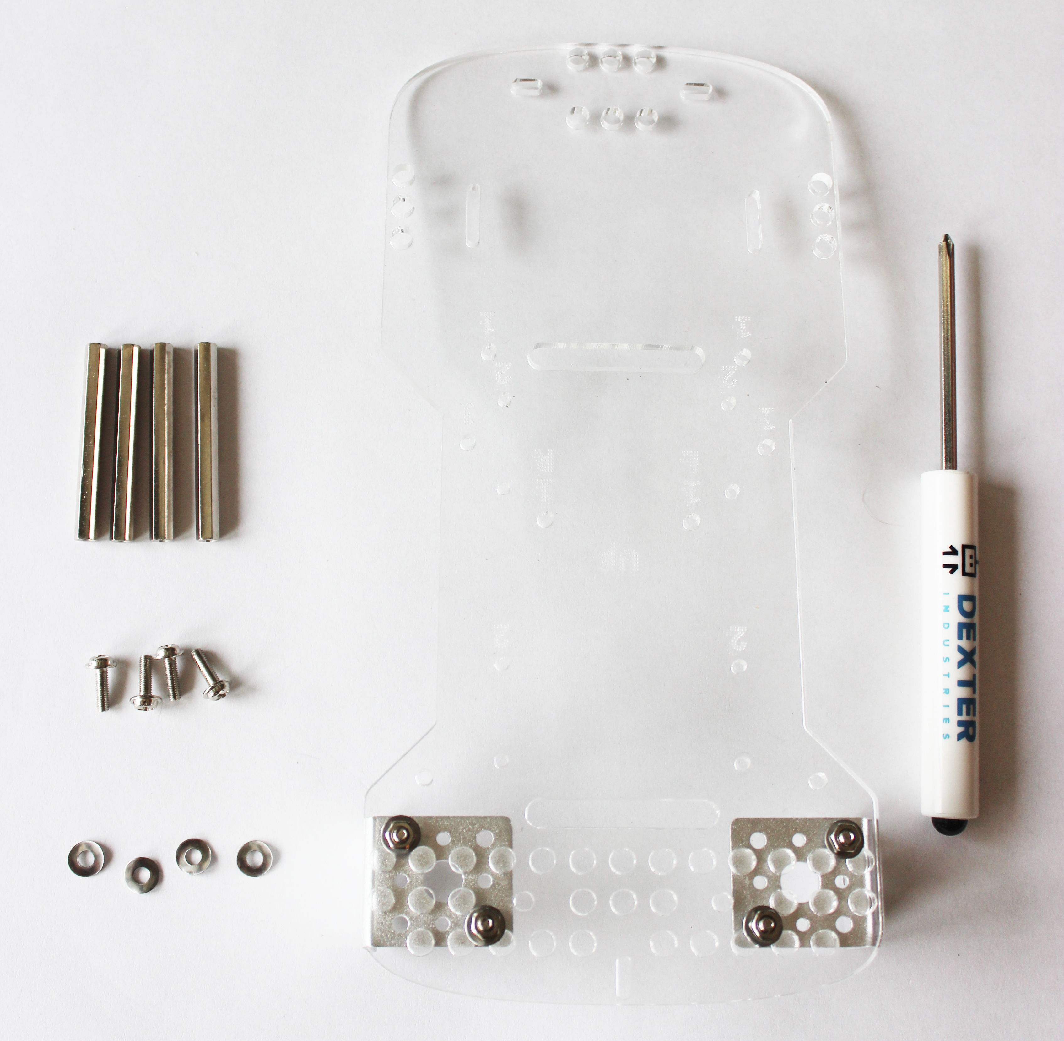
Attach both brackets.
Part 4: Attach the Canopy Spacers
What you’ll need:
- Hardware from the large bag – (D) 4 short screws, (E) 4 washers, and (J) 4 tall spacers.
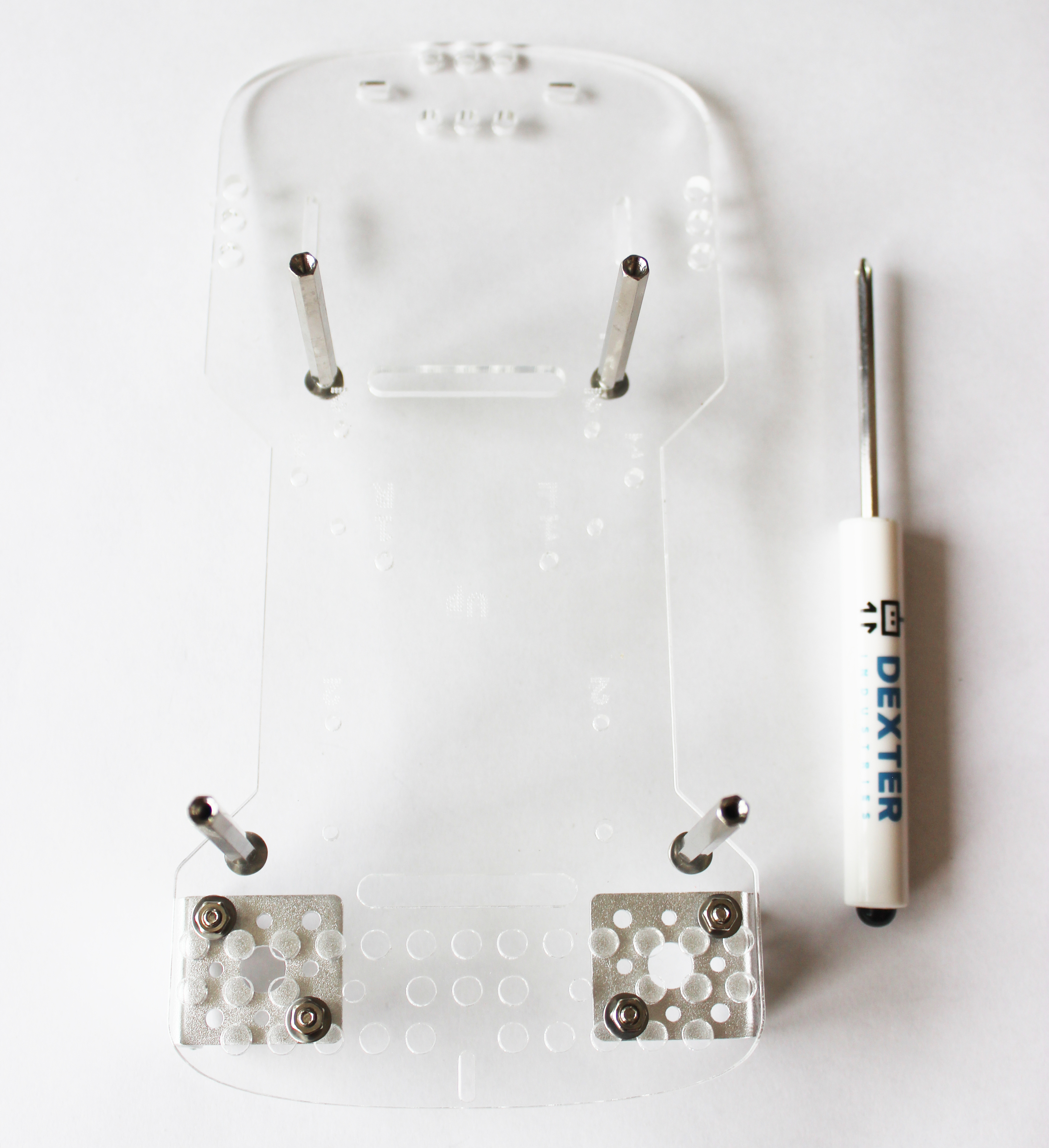
Next, attach the canopy spacers. These are the four long spacers in the large hardware bag.
Find the four holes for attaching the canopy spacers. These are the same holes we attached the canopy spacers to on the GoPiGo3 Robot Car. These have the number “1” etched next to them.
Place the washers on the screws, and insert the screws from the back, pointing upward. Screw the spacers onto the screws.
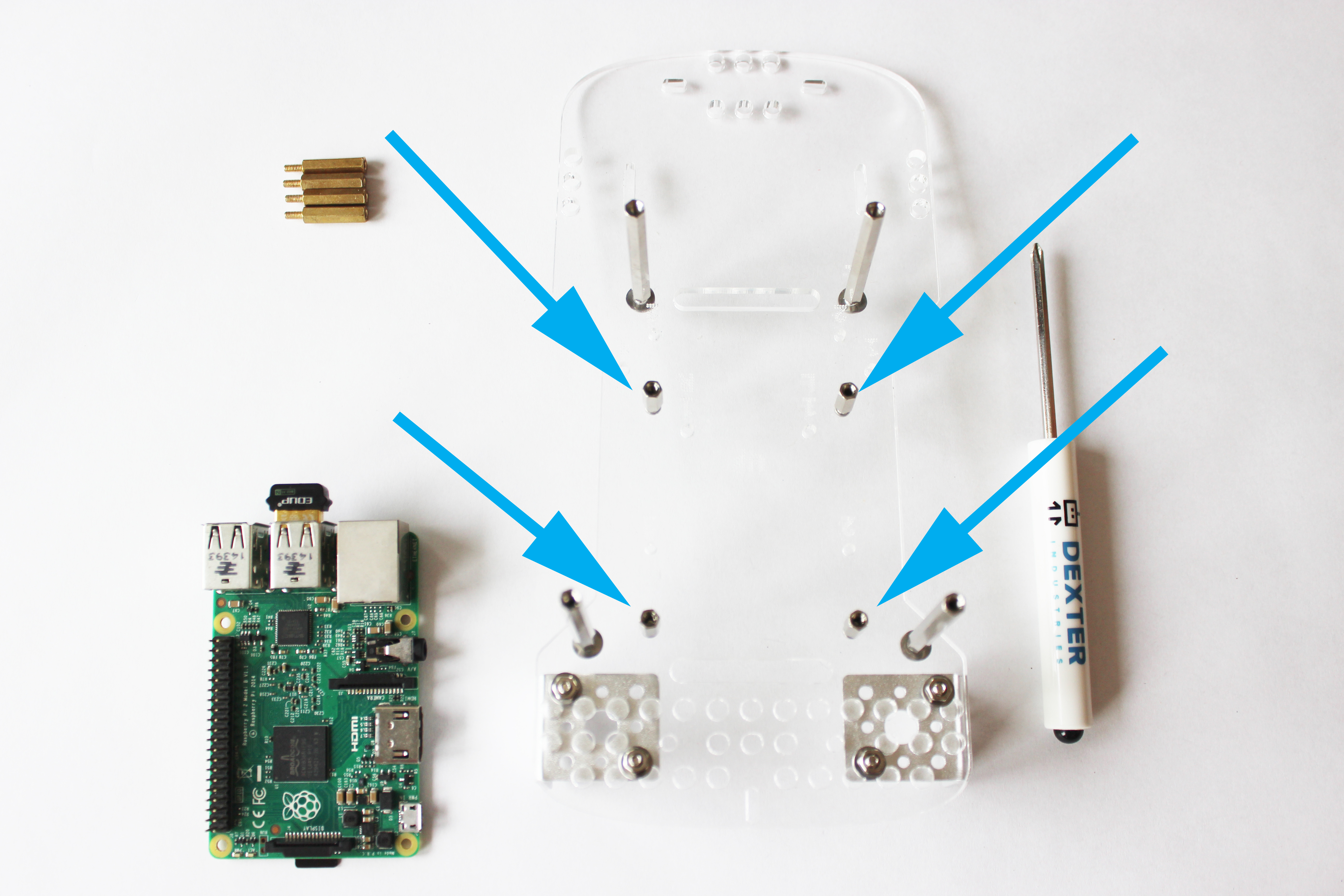
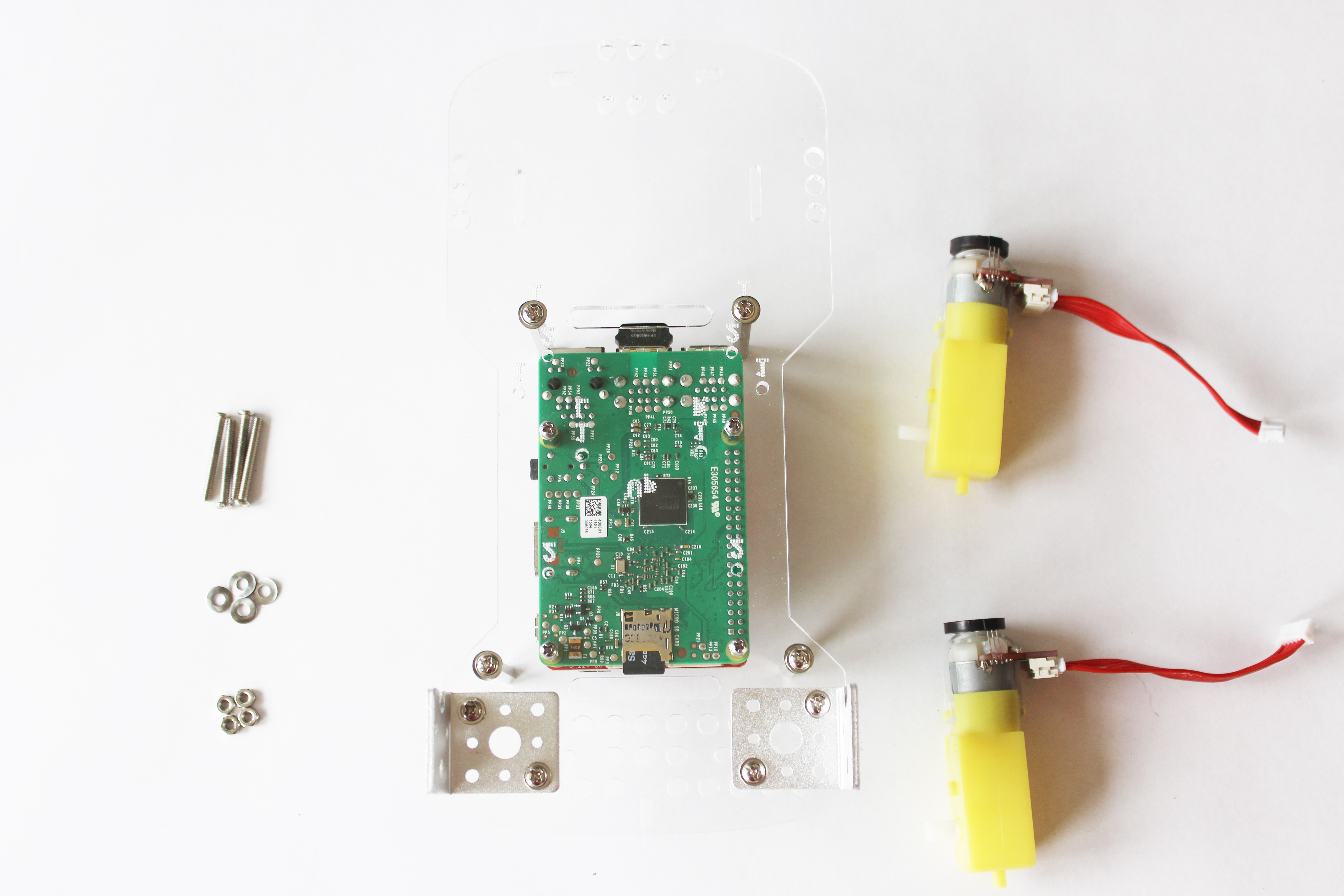
Part 5: Attach the Raspberry Pi
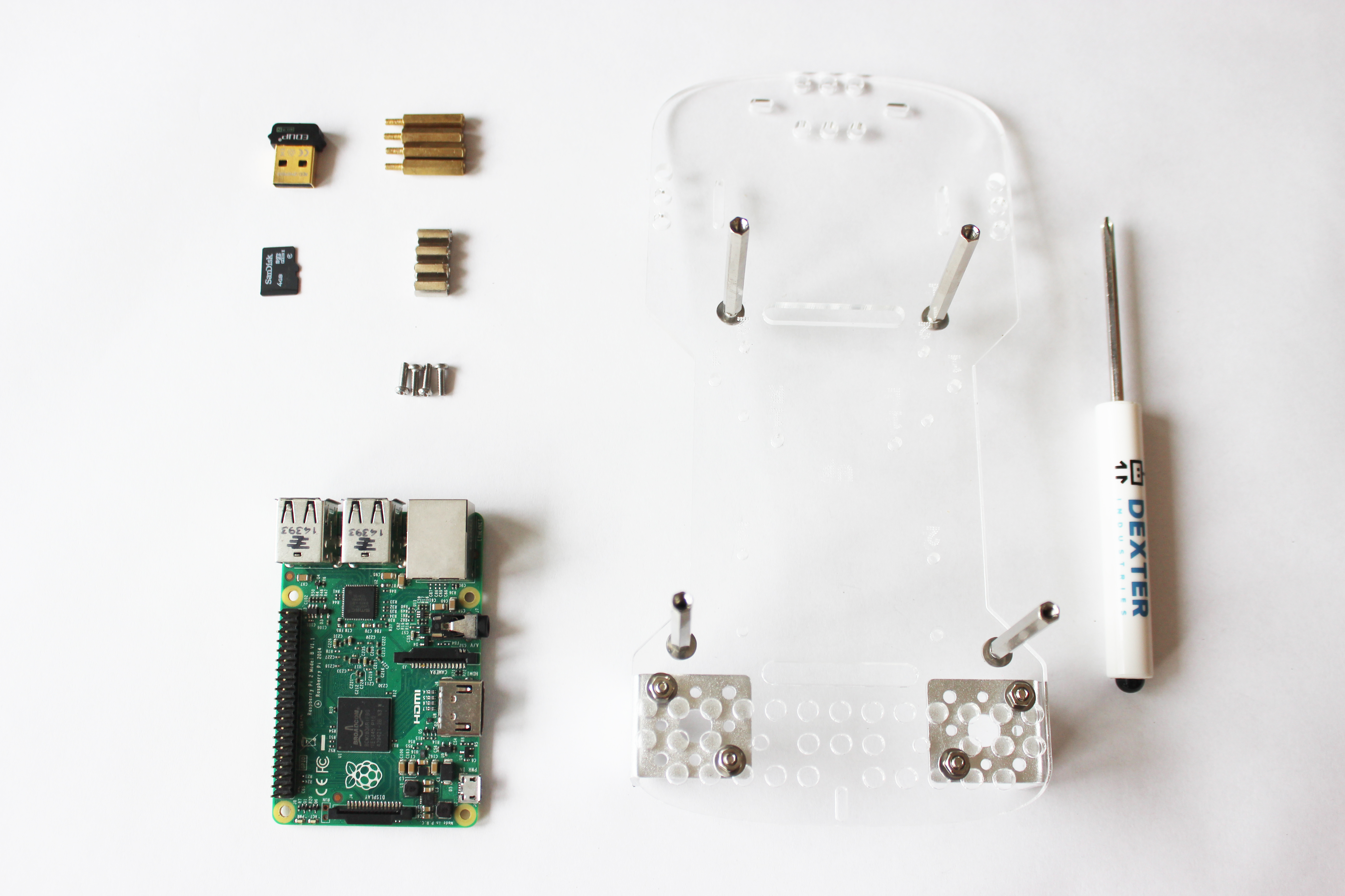
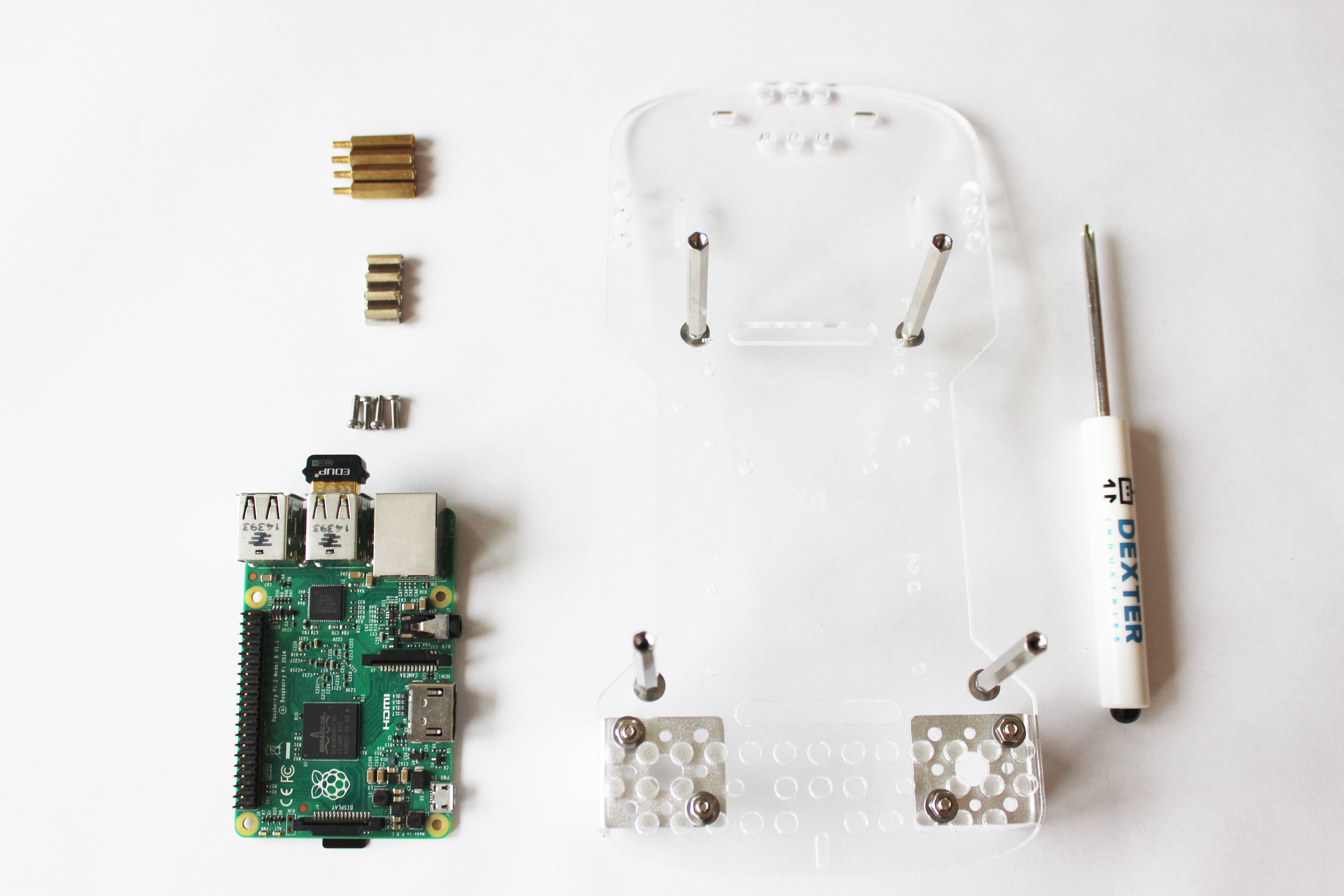
What you’ll need:
- Raspberry Pi
- SD Card
- Wifi Dongle
- Hardware from the small bag – (A) 4 short posts, (B) 4 screws, and (C) 4 male x female spacers.
Insert the SD Card and the Wifi Dongle into the Raspberry Pi.
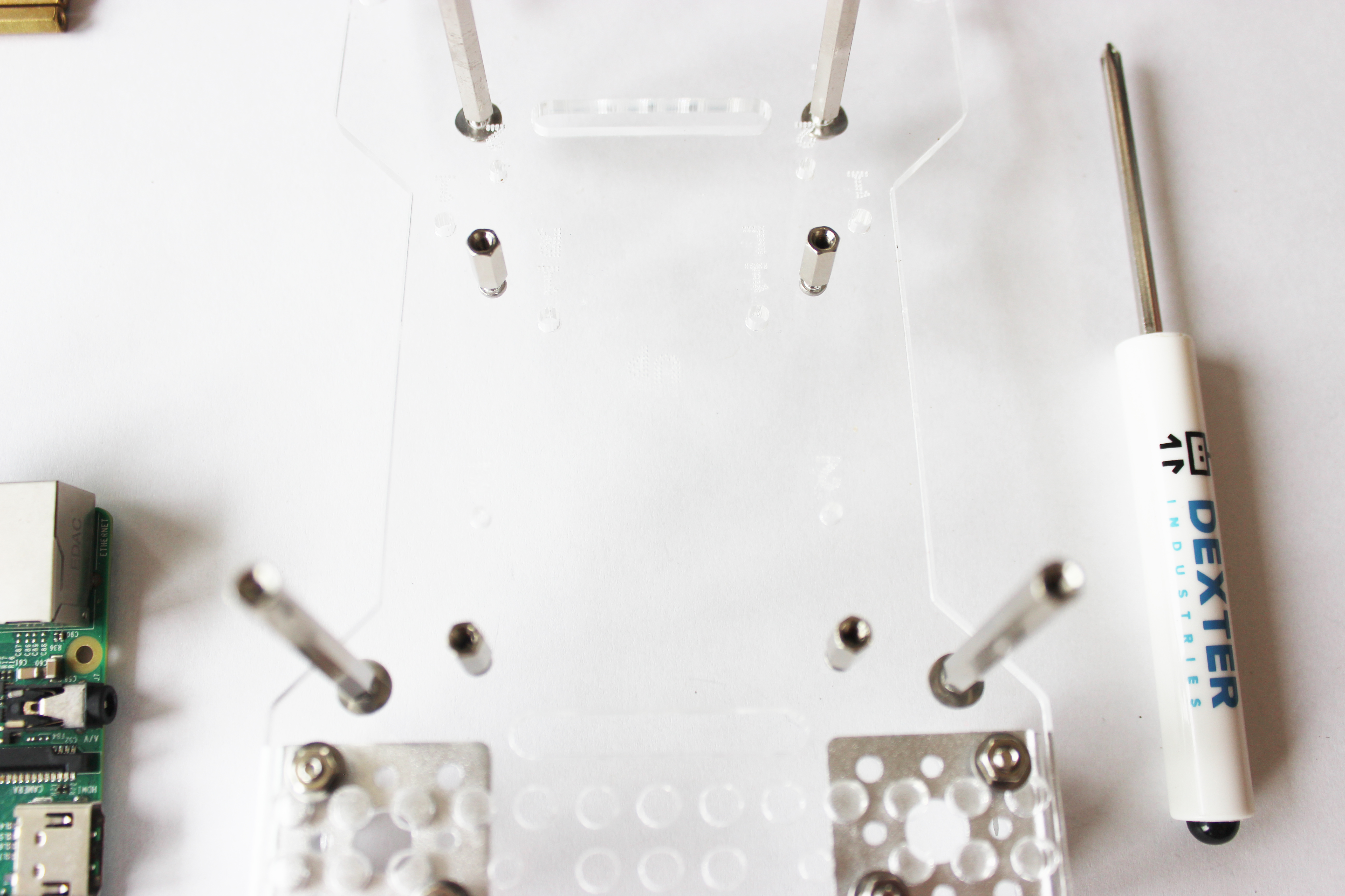
Insert the four small screws, from the back of the BalaceBot facing forward. Screw the short posts onto the screws.
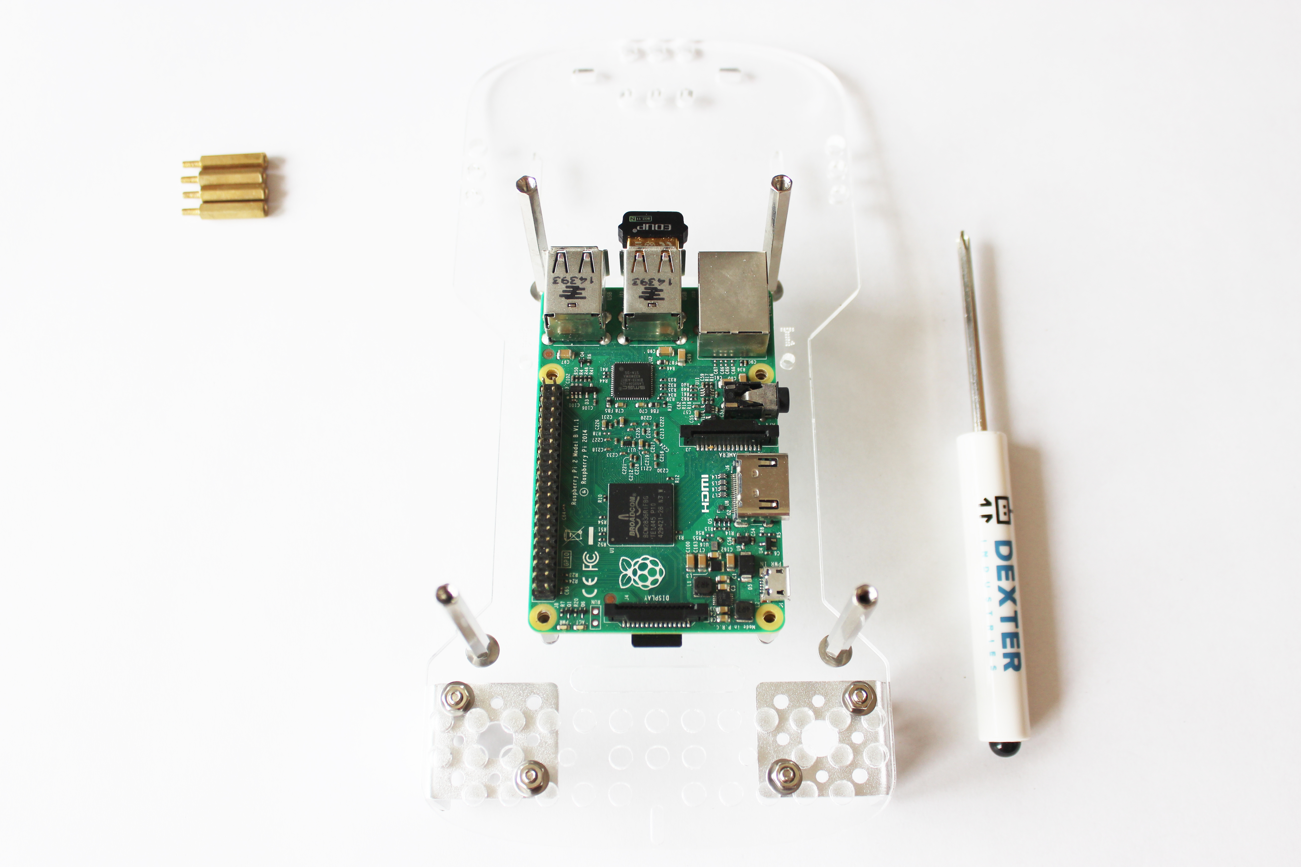
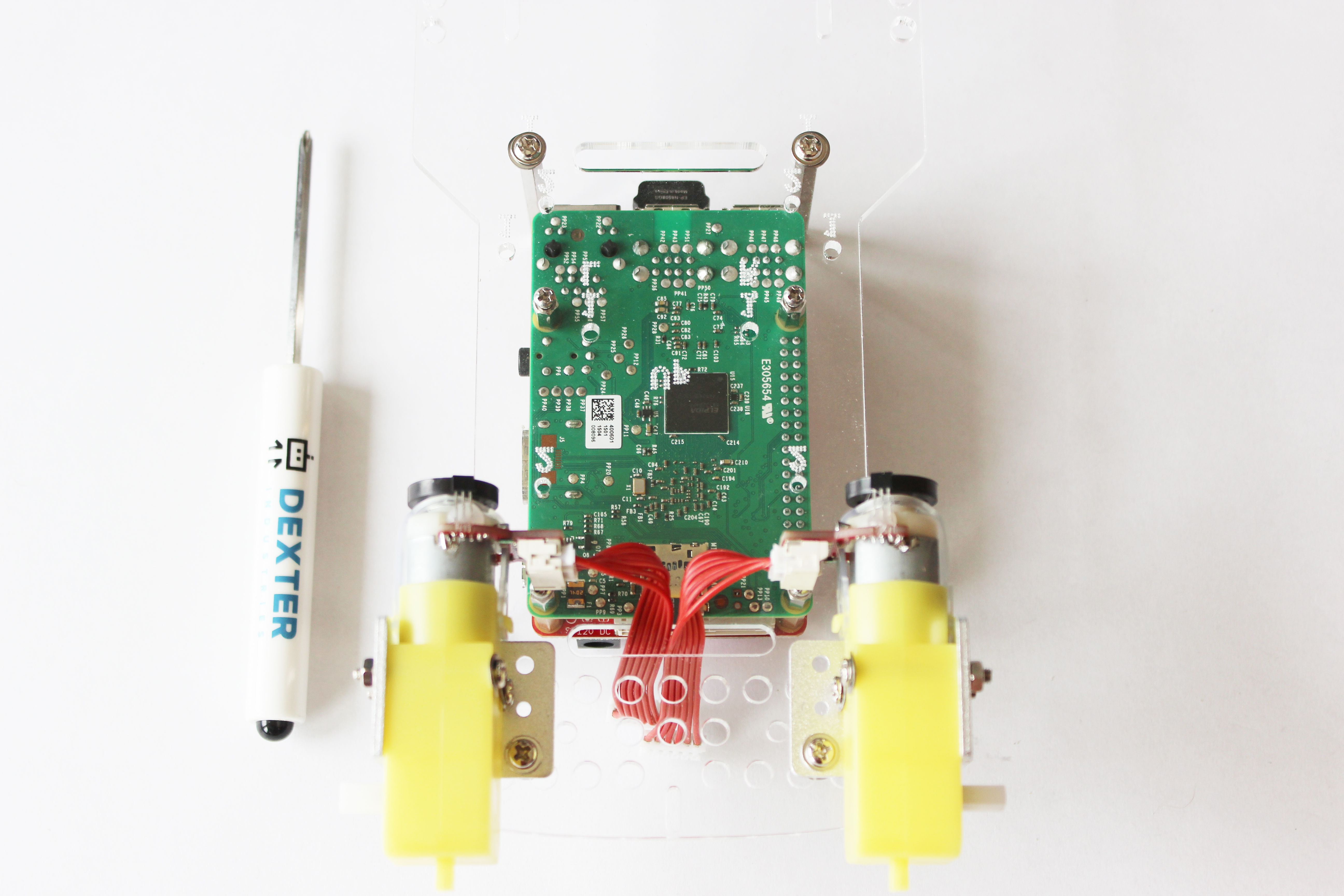
Next place the Raspberry Pi on the posts. The Pi should be placed so that the SD Card is facing the metal brackets and the USB ports are facing upwards (away from the brackets).
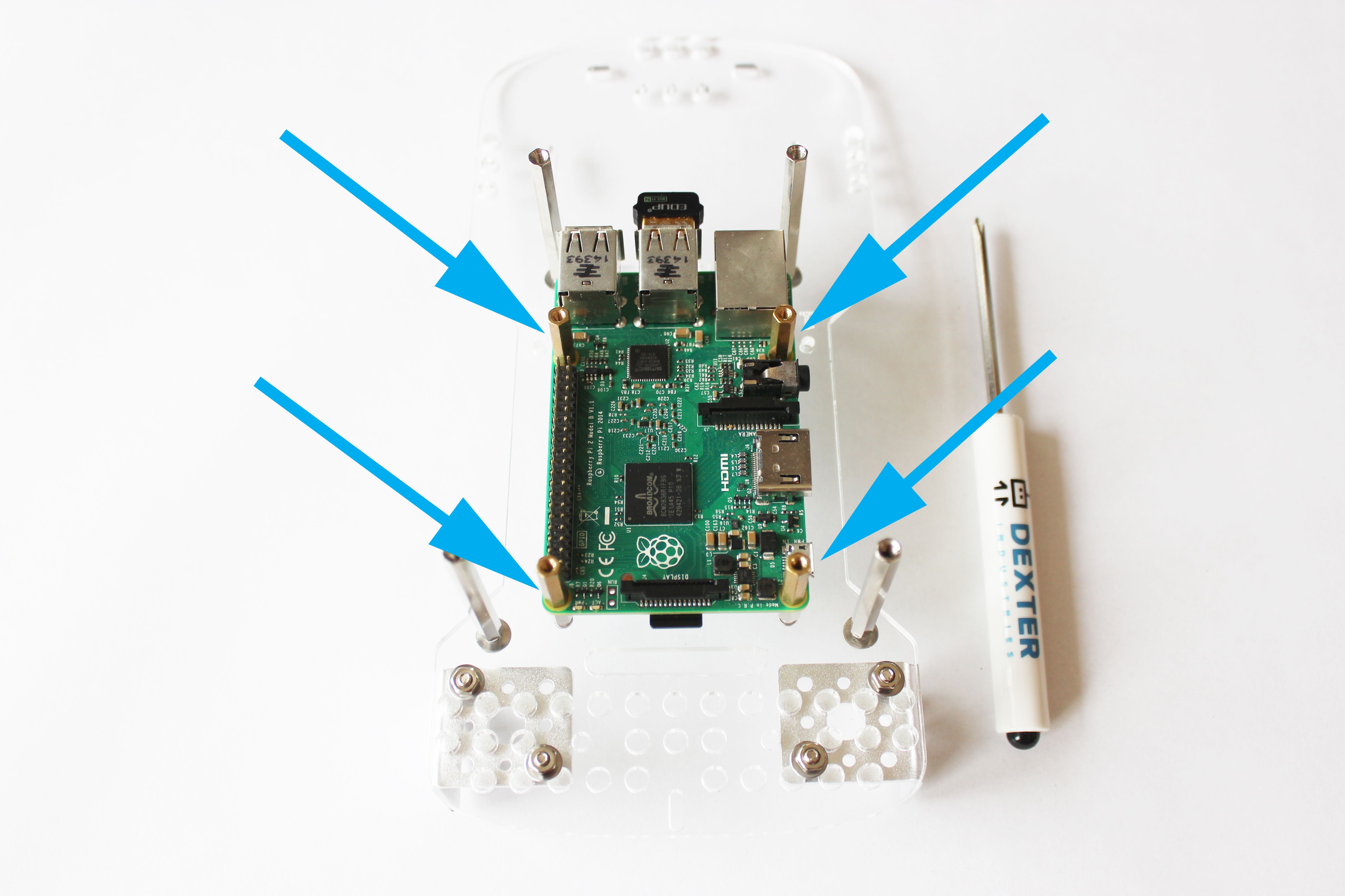
Finally, secure the Raspberry Pi by screwing the male x female posts through the mounting holes on the Raspberry Pi, into the four posts.
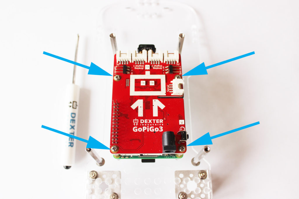
Part 6: Attach the GoPiGo Red Board
What you’ll need:
- GoPiGo3 Board – The red board.
- Hardware from the small bag – (B) 4 screws.
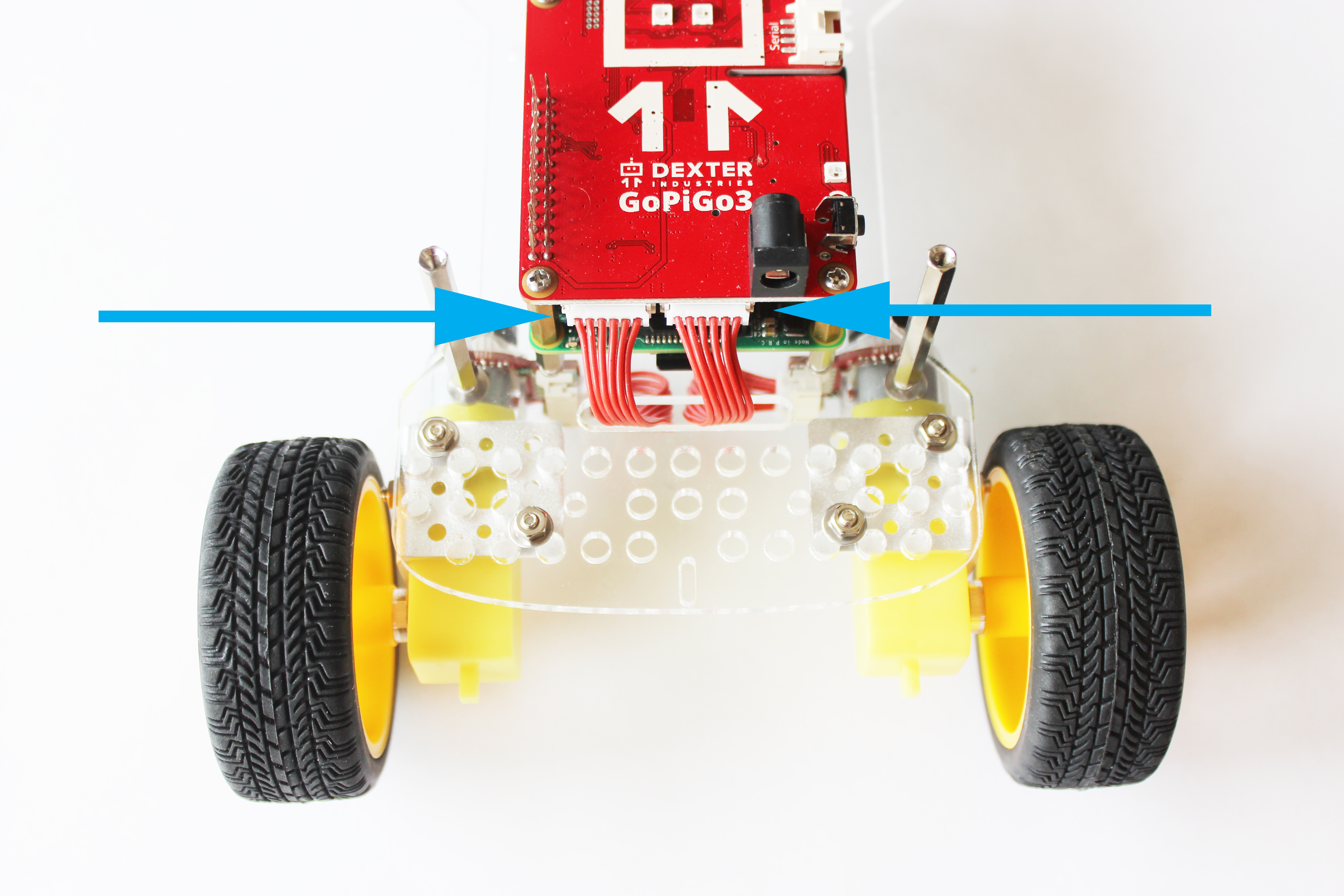
Slide the read board over the green board, aligning the pins. The read board should line up with the four brass posts on the Raspberry Pi.
Screw the screws through the red GoPiGo3 board and into the brass posts.
Part 7: Attach the Motors
What you’ll need:
- GoPiGo3 Board – The red board.
- Hardware from the small bag – (B) 4 screws.
- Hardware from the large bag – (G) 4 long screws, (E) 4 washers, (F) 4 nuts.
- Yellow Motors
- Red Motor Cables
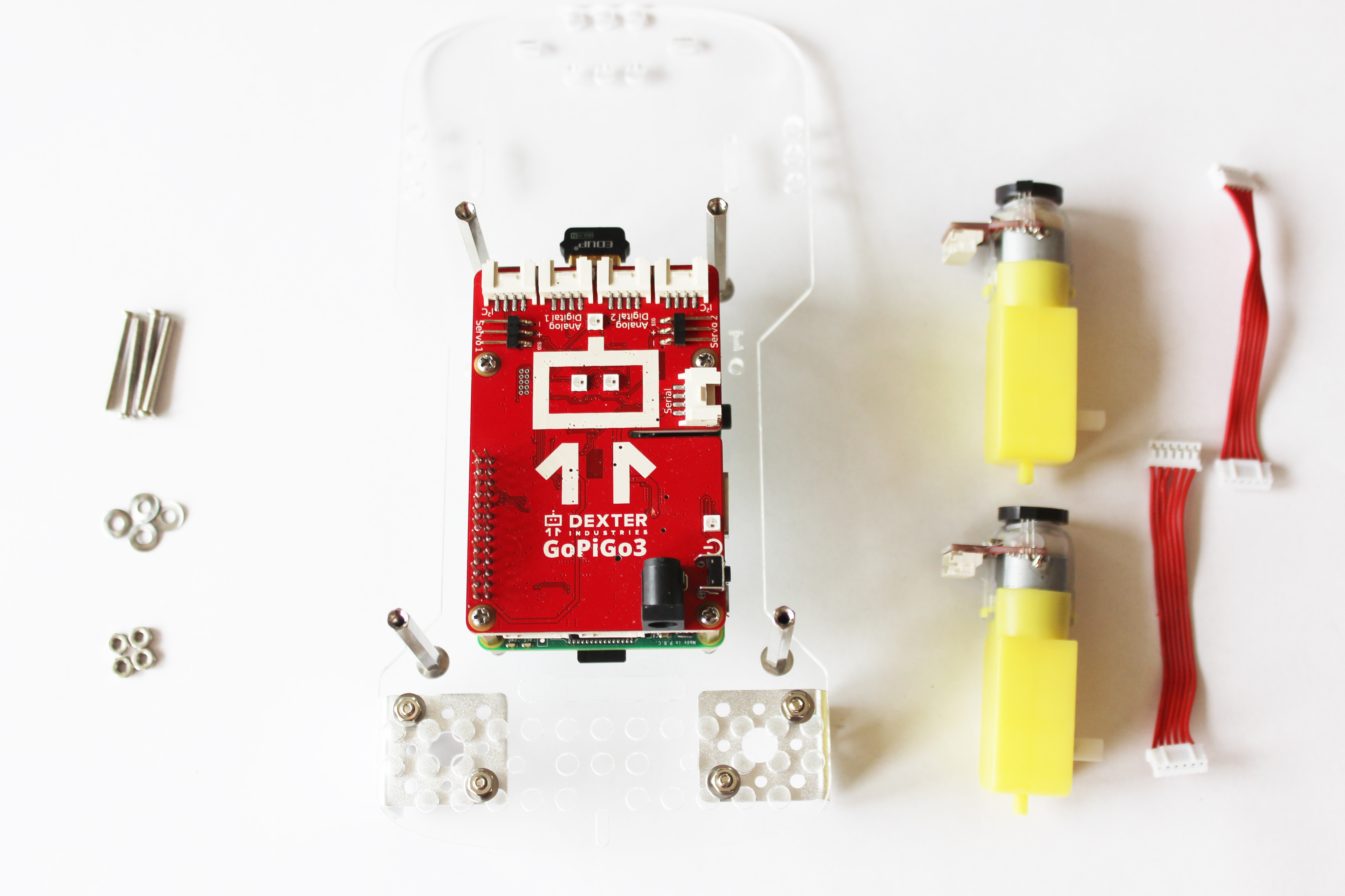
Attach the red cables to the yellow motors.
Slide the washers onto the long screws.
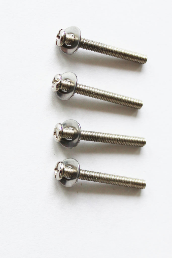
Slide the screws through the two holes on the motors, and slide the screws through the metal brackets. The magnets on the motors should be pointing upward.
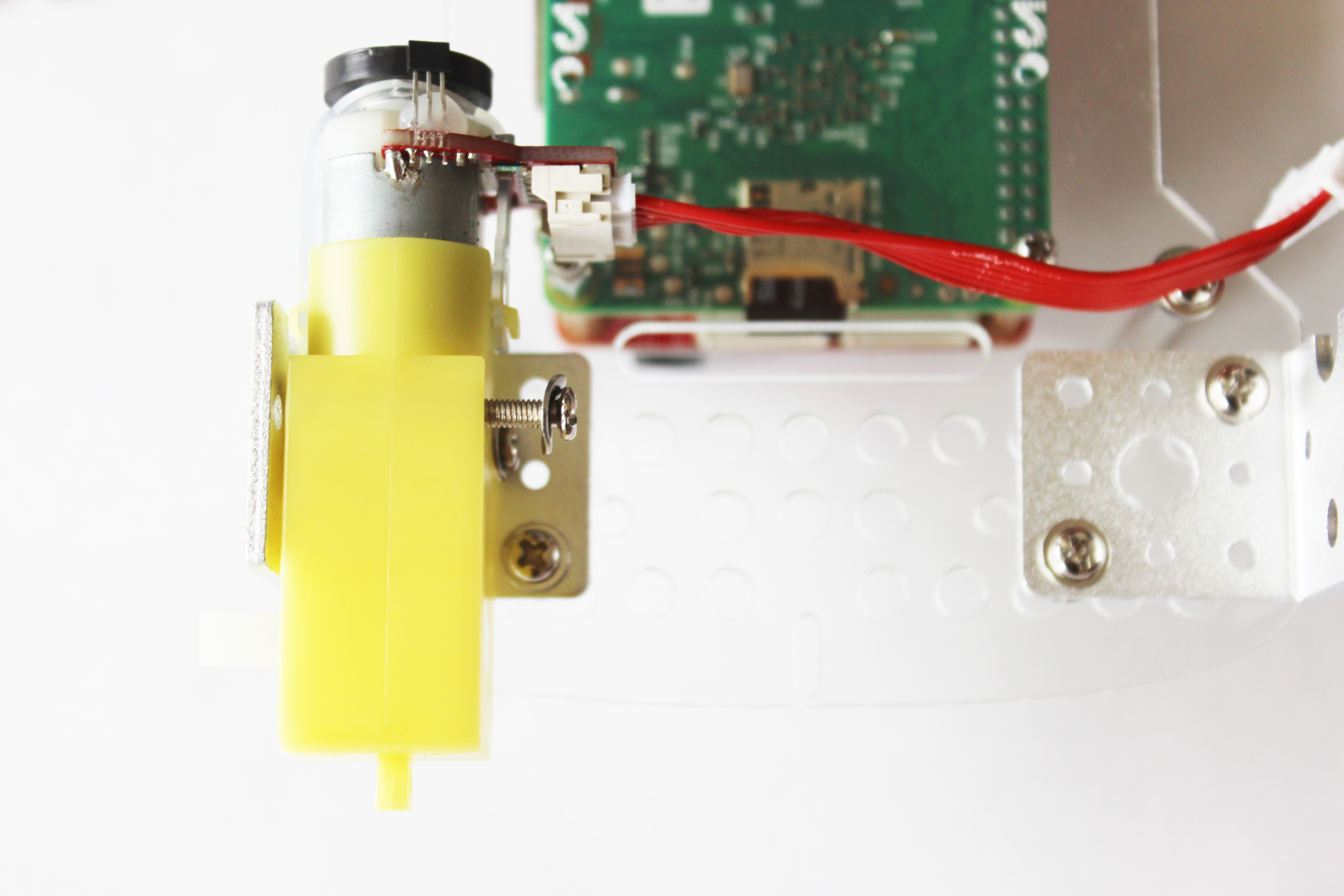
Attach the nuts to the other end of the screws and tighten until the washers flatten.
Part 8: Attach the Wheels
What you’ll need:
- Wheels – 2 yellow wheels.
- Hardware from the large bag: (H) 2 small round acrylic spacers
First, slide the spacers onto the white motor axles.
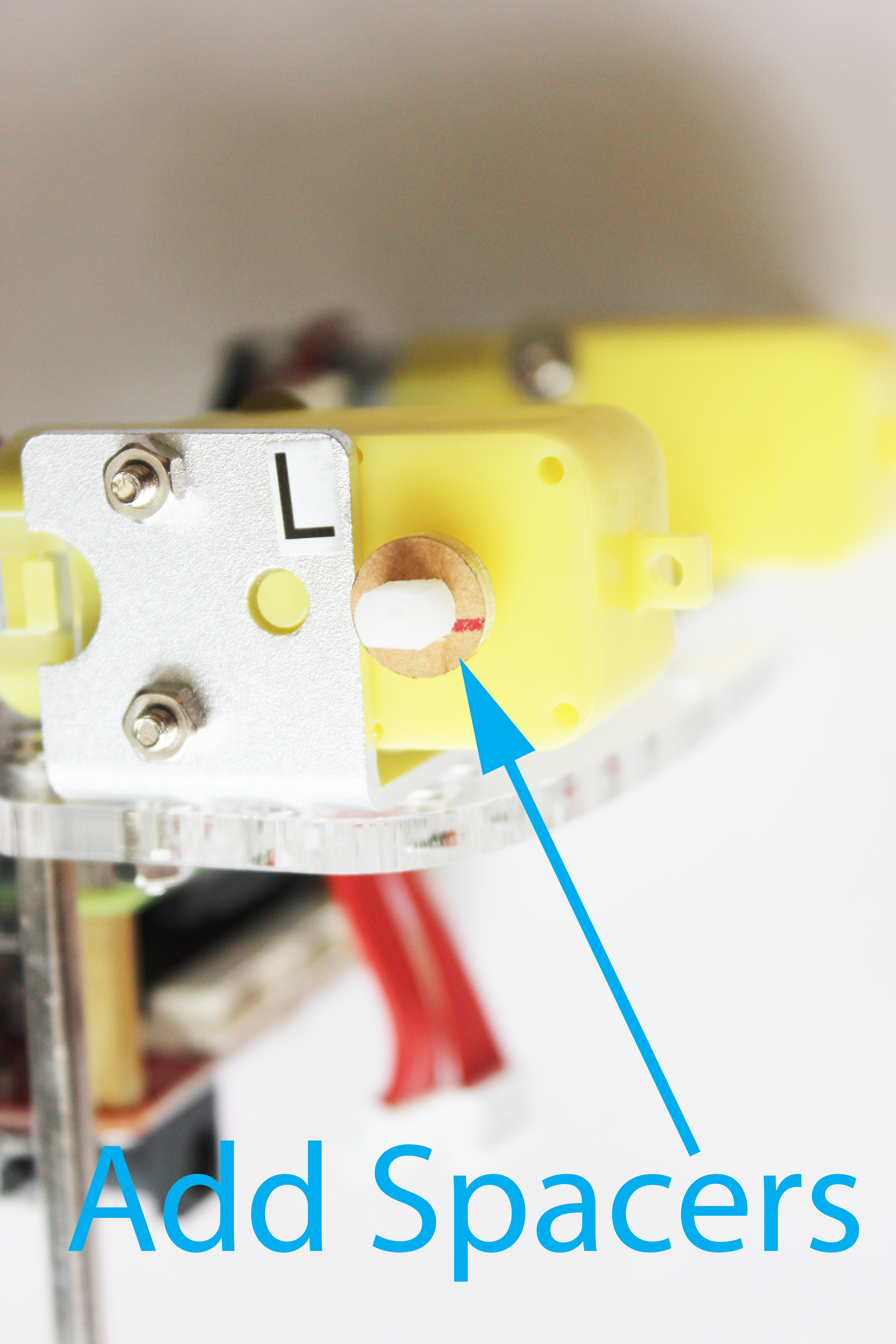
Next, attach the yellow wheels to the motors.
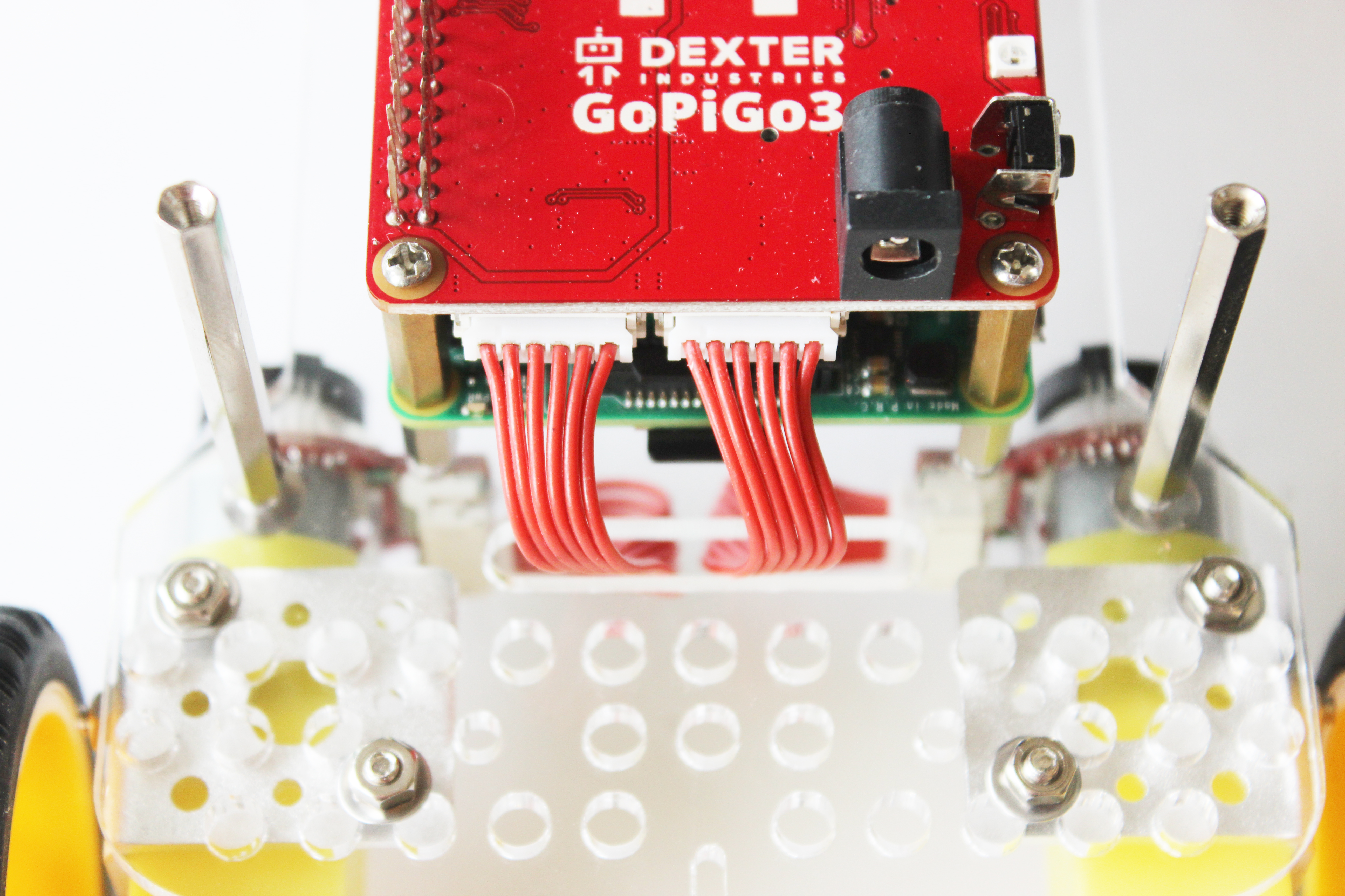
Finally, attach the motor cables to the motor cable ports.
Part 9: Attach the Canopy
What you’ll need:
- Hardware from the large bag: (E) 4 washers, (D) 4 small screws
- Acrylic canopy
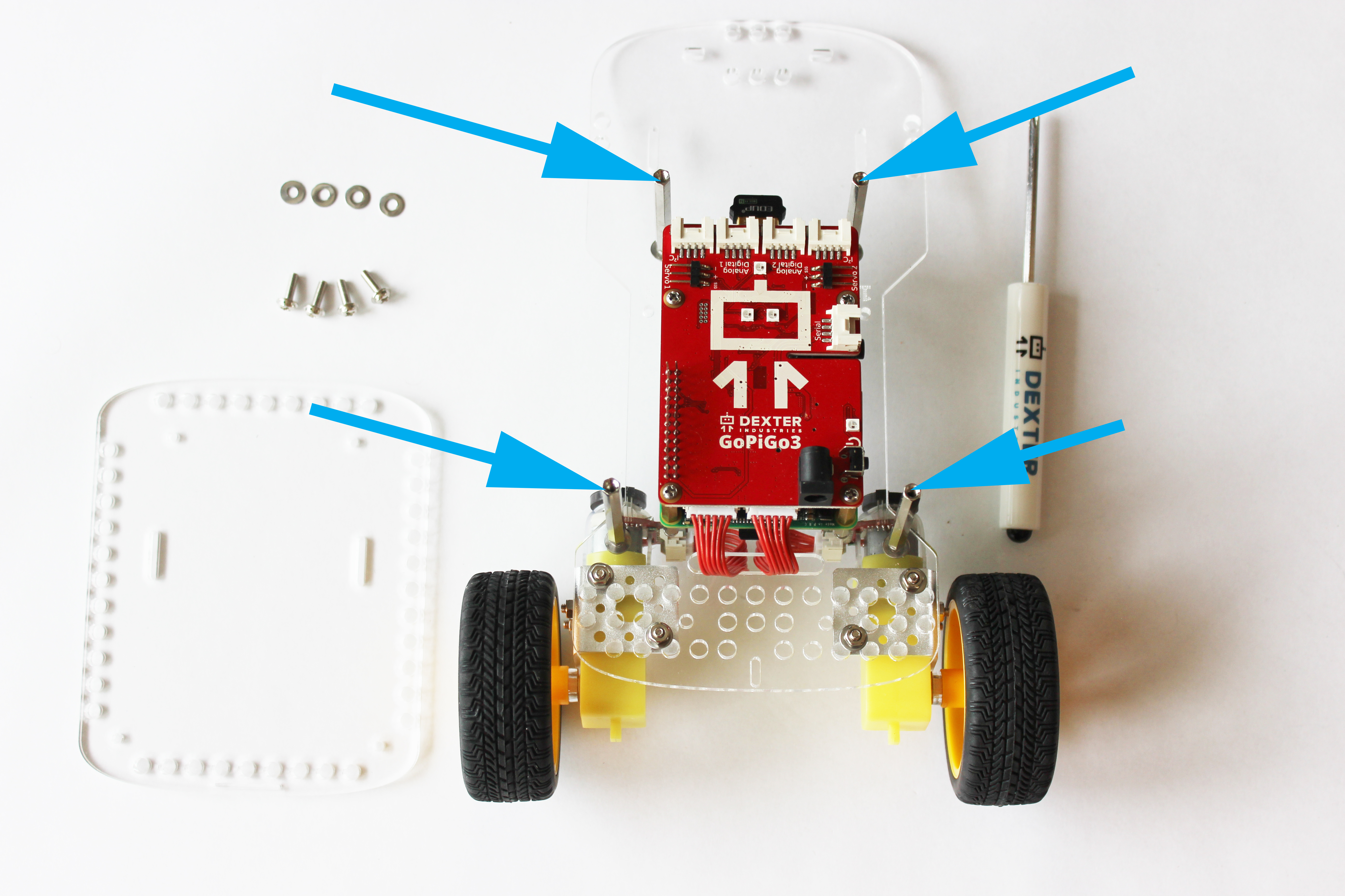
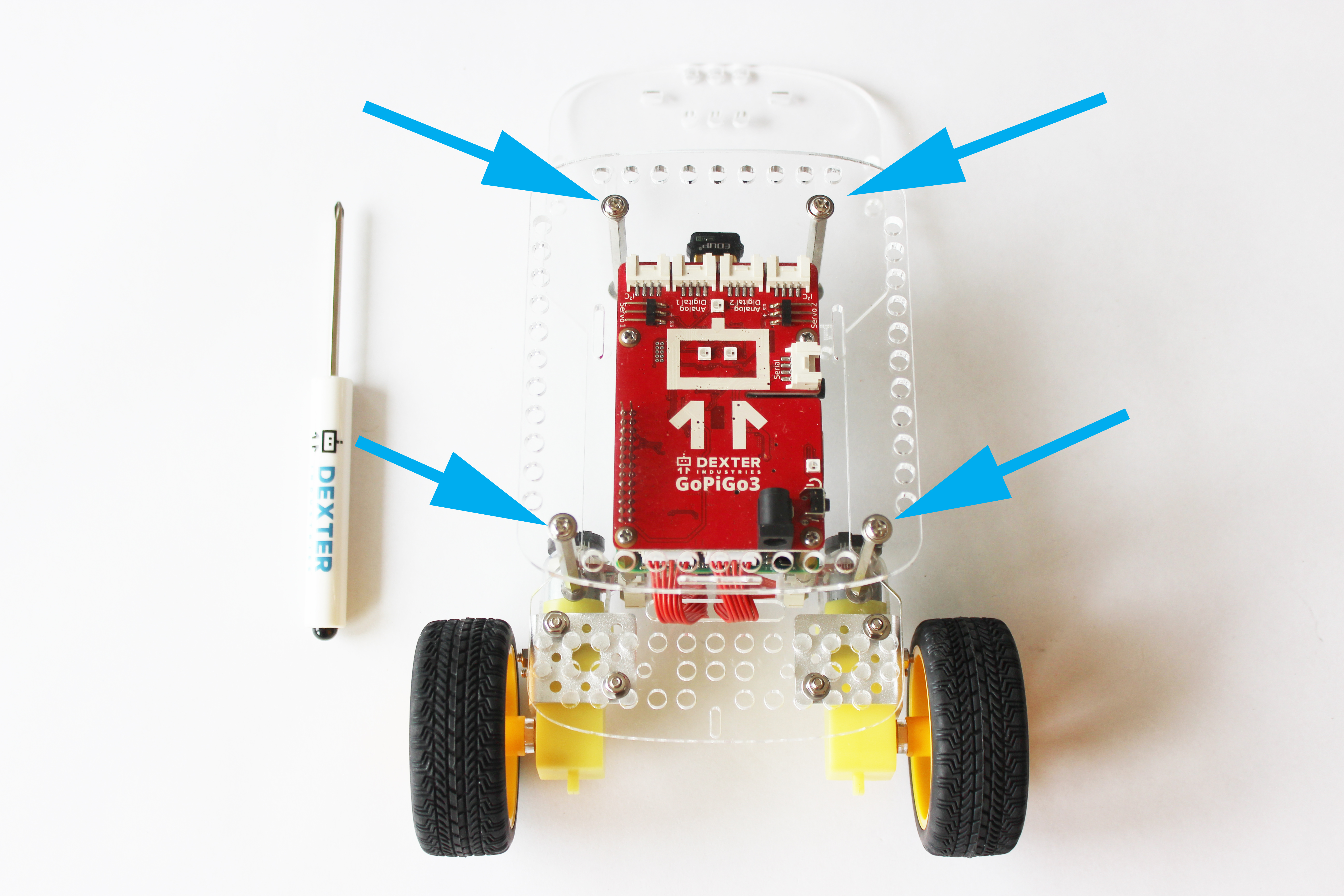
Attach the top:
- Place one washer on each screw.
- Place the acrylic canopy on top of the four tall silver posts. There is a small slot cutout on the acrylic for a camera that should be towards the front of the GoPiGo, and the two battery pack slot cutouts should face towards the back.
- Secure the acrylic canopy in place with the screws.
Part 10: Attach the Batteries
What you’ll need:
- Battery Pack
- BalanceBot Battery Pack Cable
- Velcro Strap
- 8 AA batteries
The BalanceBot Pack comes with a special Battery Pack Cable. This cable is approximately 20 cm long, and has a 90 degree bent barrel jack adapter.
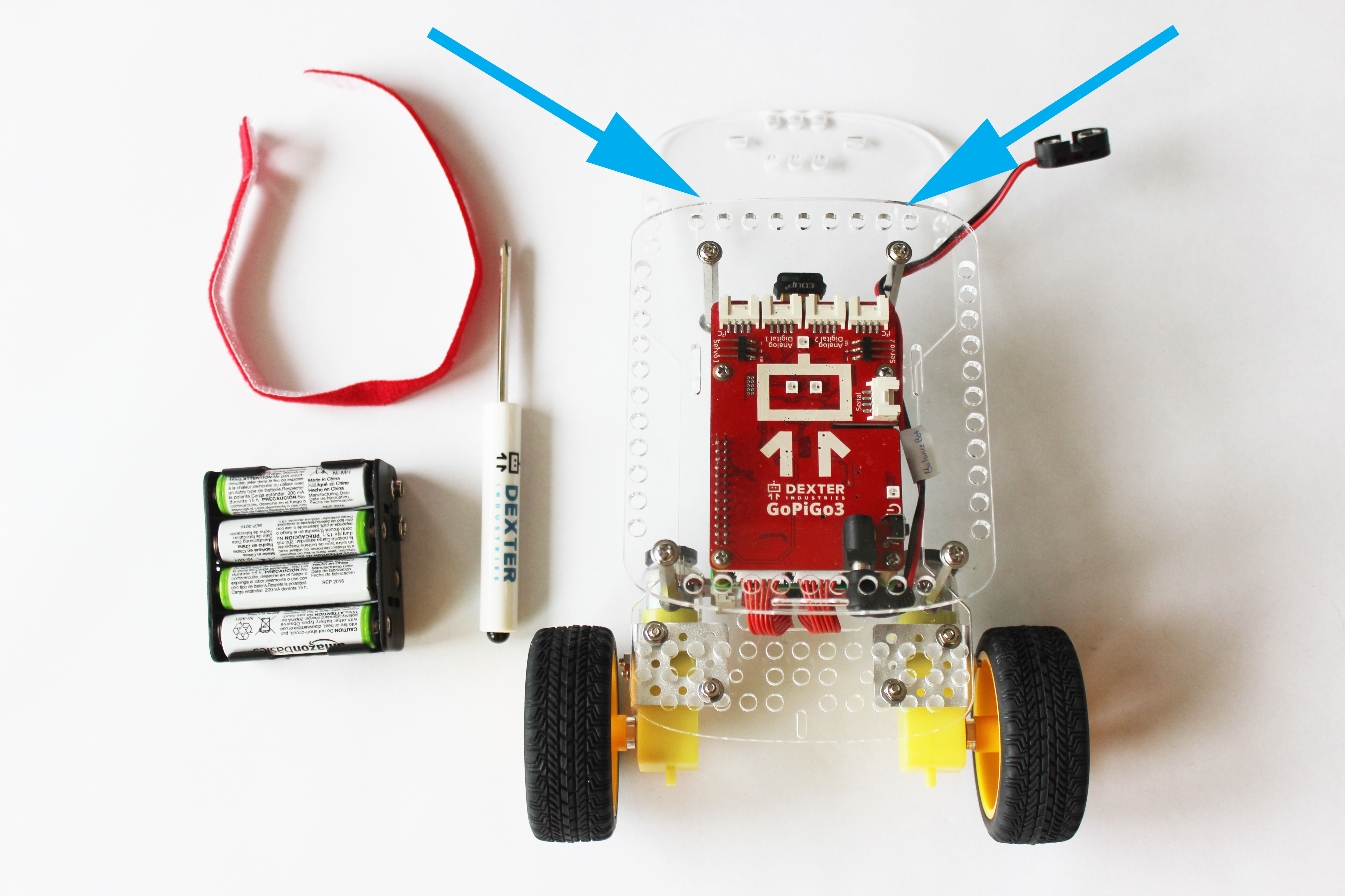
Thread the velcro strap through the battery strap cutouts on the GoPiGo3 acrylic body.
Secure the velcro strap around the battery pack and connect the BalanceBot Battery Pack Cable to the Battery Pack.

Part 11: Attach the Sensors
What you’ll need:
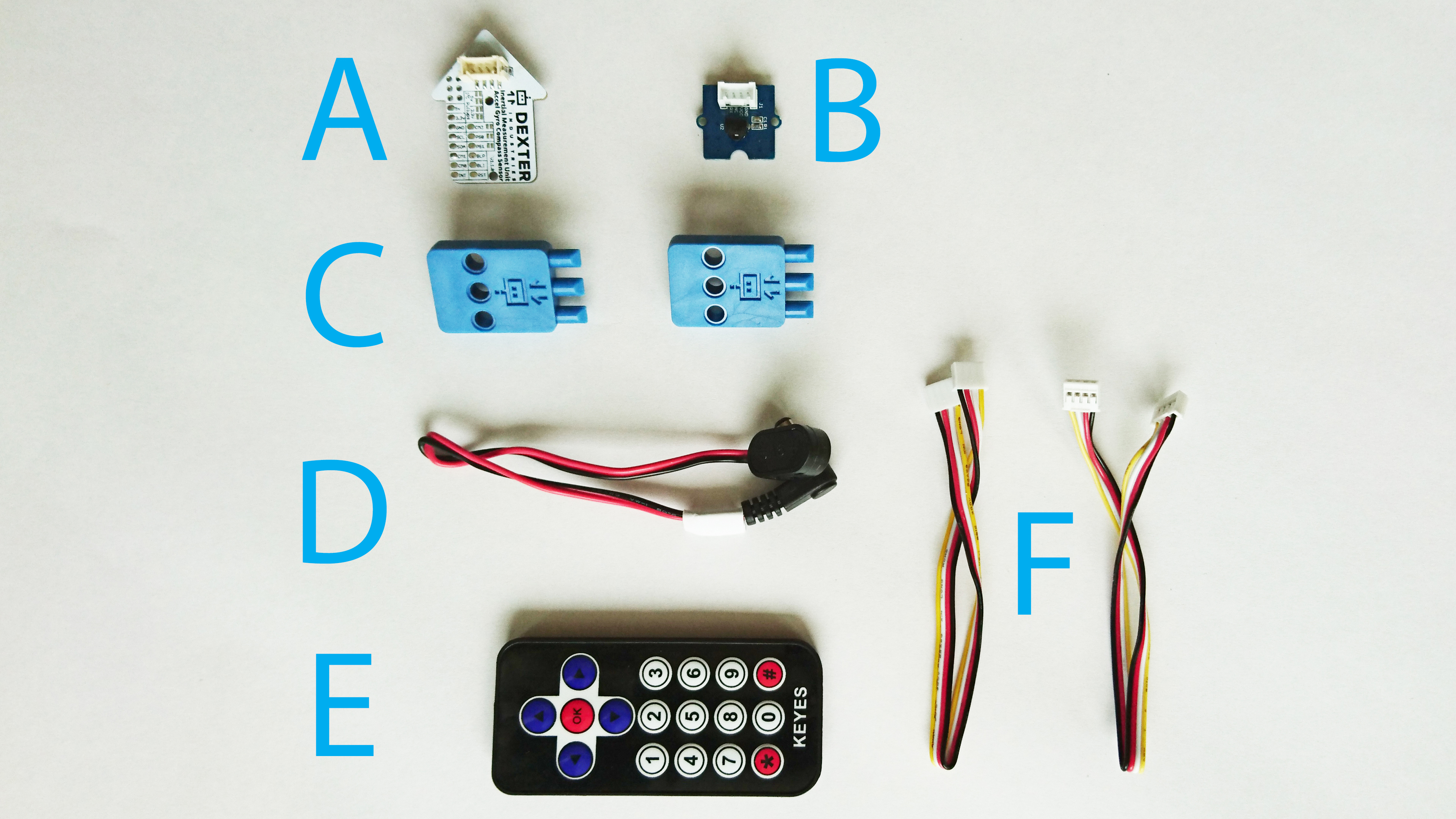
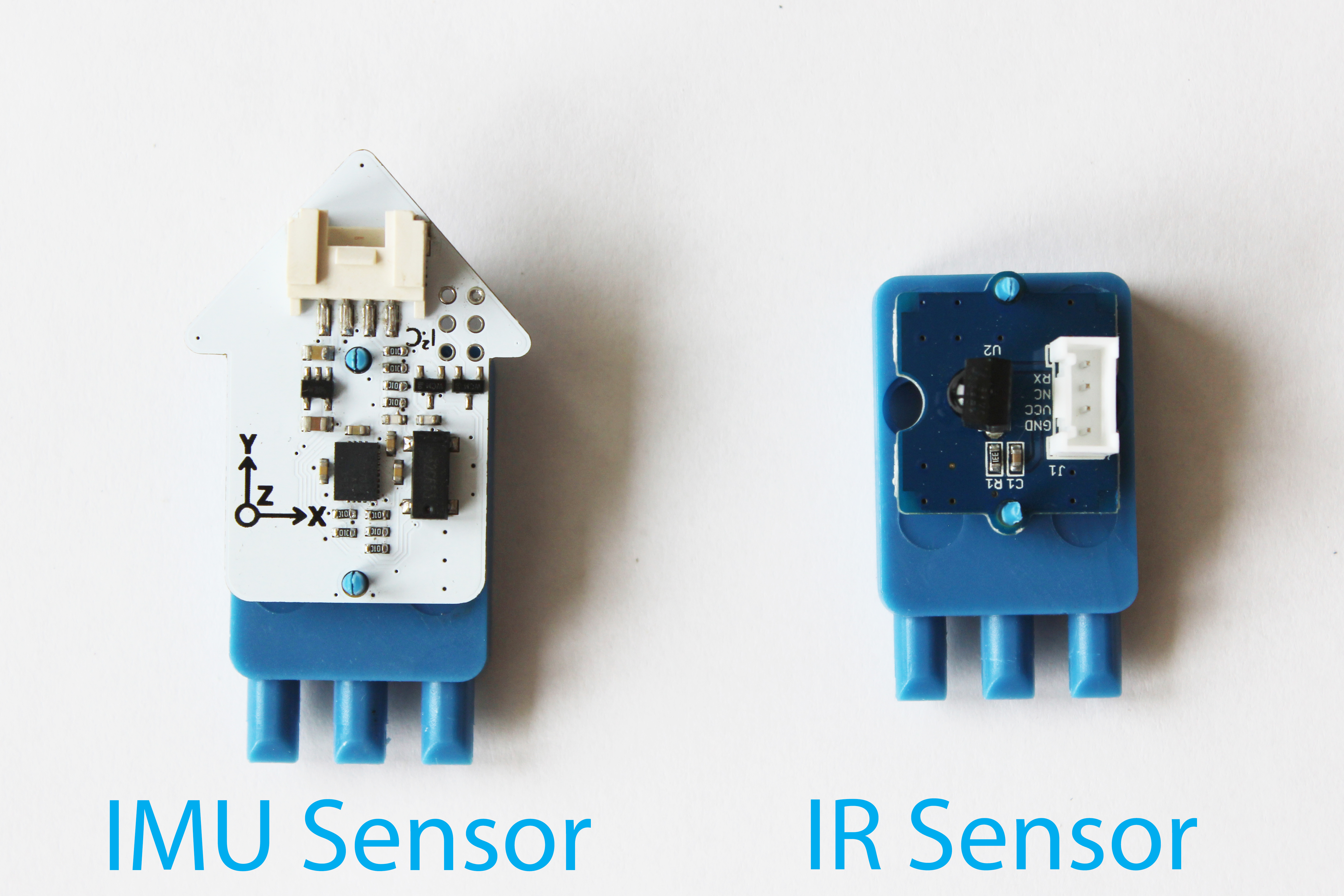
- BalanceBot Pack – Includes an Inertial Motion Sensor (IMU) (A), Infrared Sensor (B), 2 blue Dexter Industries Sensor Mounts (C), 1 battery pack cable (we used this in Part 10 already!) (D), 1 Infrared Remote (E), and 2 sensor cables (F).
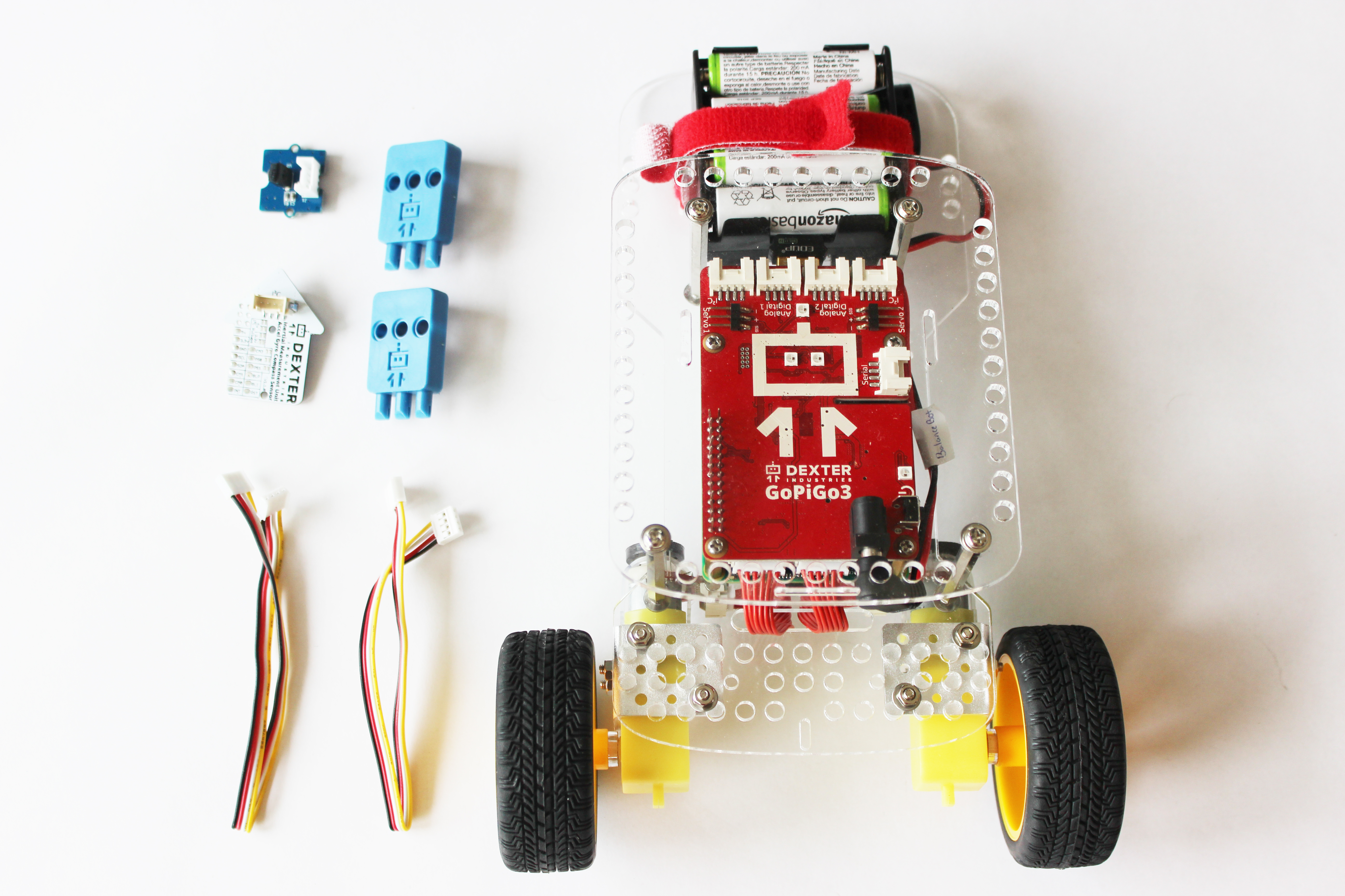
Attach the sensors to the Sensor Mounts. Pay close attention to the orientation of the IMU sensor: the arrow should be pointing upwards, and the axis indicator (that shows x, y, and z axes) should be visible.
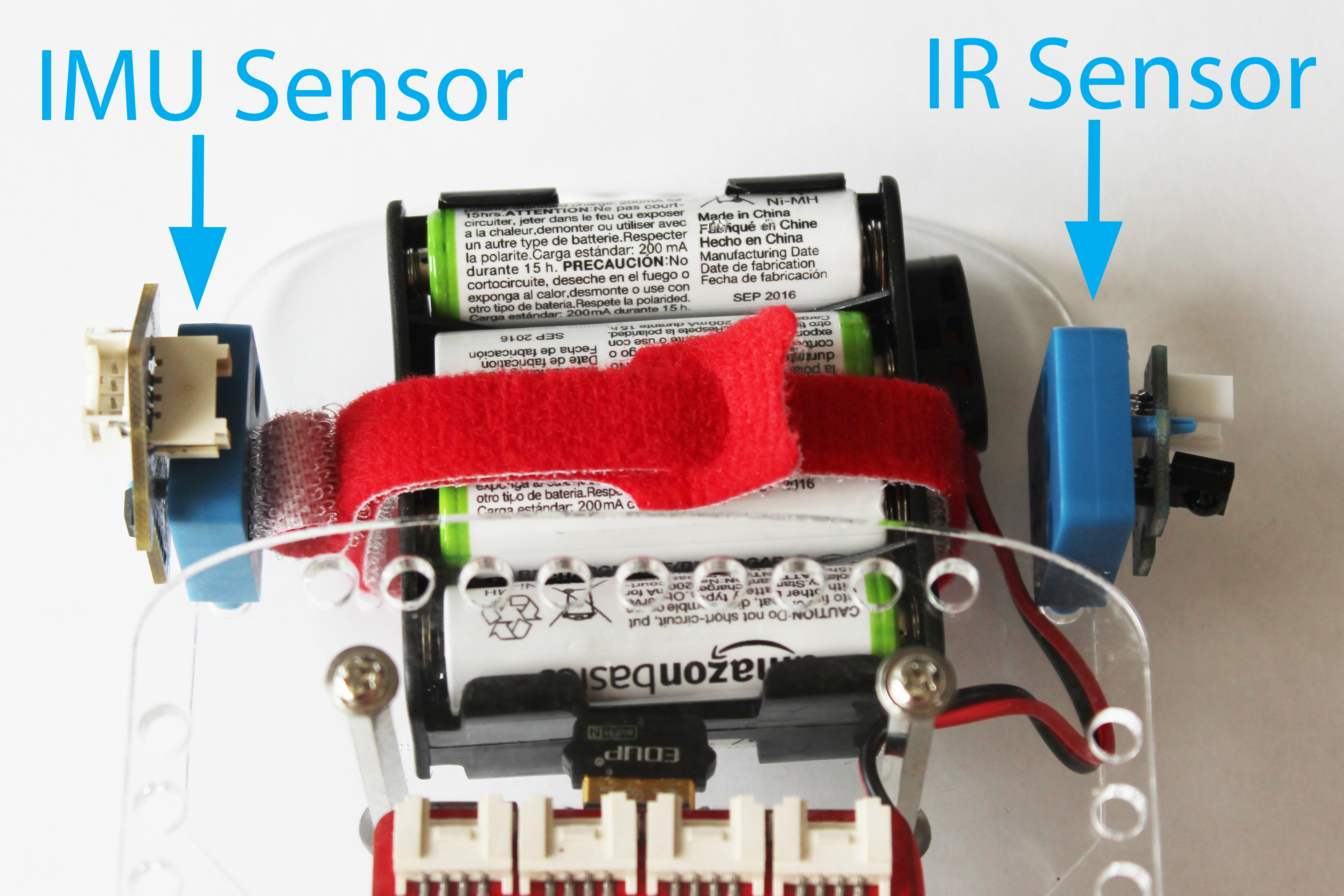
Attach the sensors to the GoPiGo3 BalanceBot. Using the two sets of holes nearest the velcro battery strap, place the IMU on the left side of the robot and the IR sensor on the right of the robot.
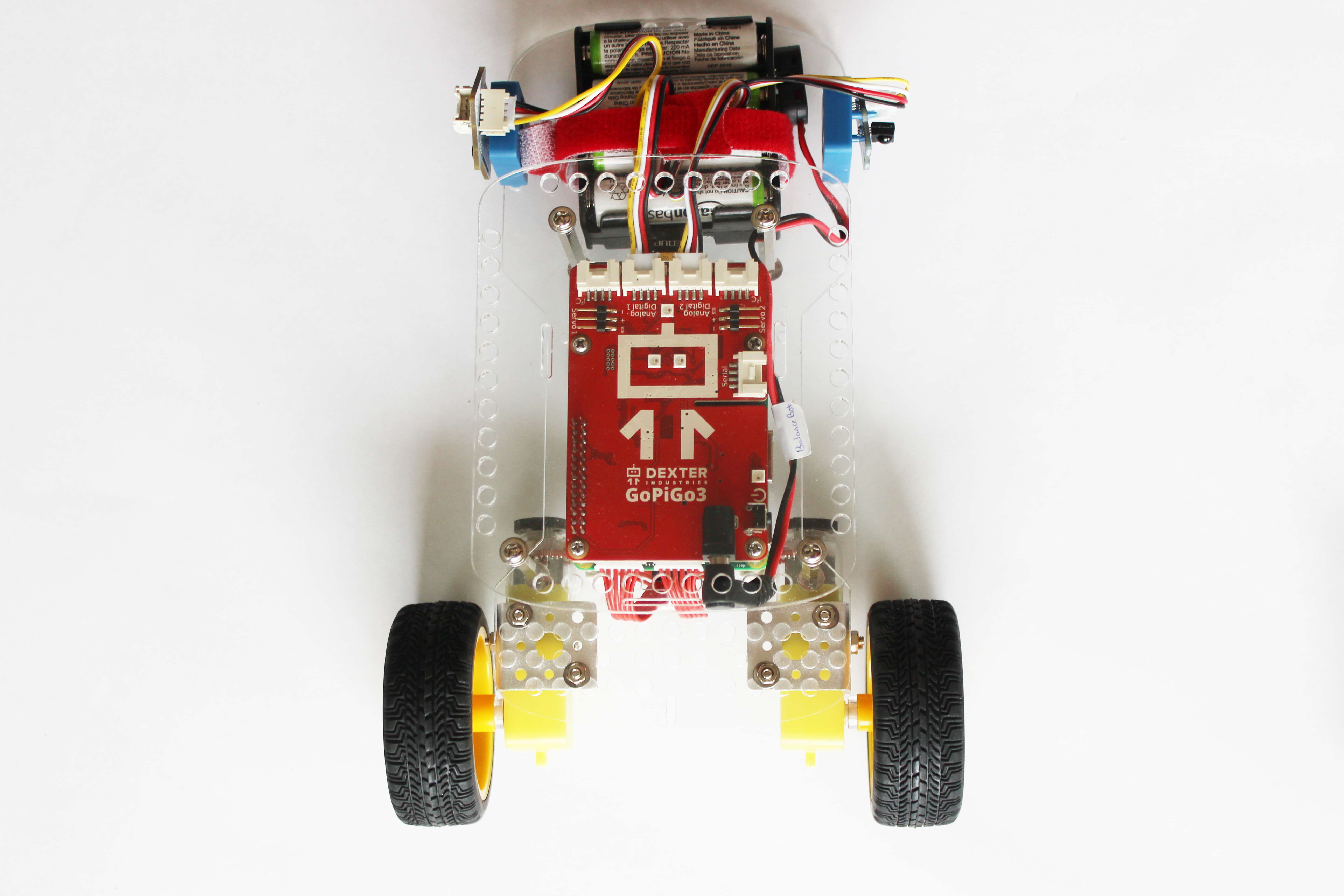
If the sensors are attached correctly, they should both be on the outside of the robot. The IMU should be pointing forward.
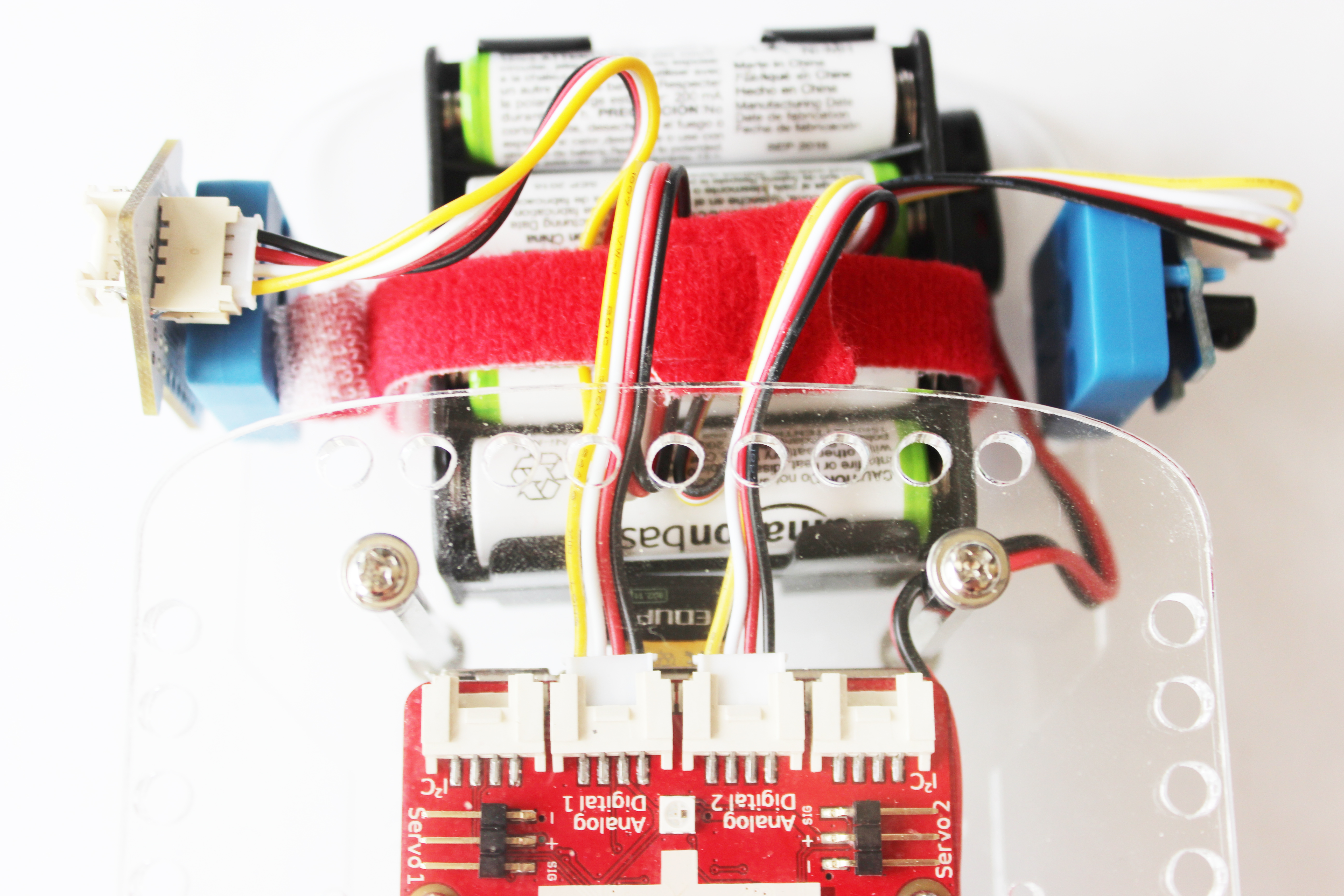
Finally, connect the sensors to the red GoPiGo3 board. The IR sensor connects to Analog Digital 2 port, and the IMU sensor connects to the Analog Digital 1 port.
A closeup of the sensors attached to the BalanceBot, and connected to the GoPiGo3 board.
Finished! Now Connect! If you already know how to connect, here’s how to run the BalanceBot program.
Want to attach the Raspberry Pi Camera, Distance Sensor, or Ultrasonic to your GoPiGo3? Click here!
Questions?
Need some help? Have a question or a suggestion? Ask on the forums here.