Step 1 – BrickPi3 Assembly
In this step, we will go over the three steps of BrickPi3 Assembly. The BrickPi3 and case will fit the Raspberry Pi B+, Raspberry Pi 2, and Raspberry Pi 3.

BrickPi3 Assembly
1. Insert the SD Card
Before You Begin
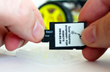
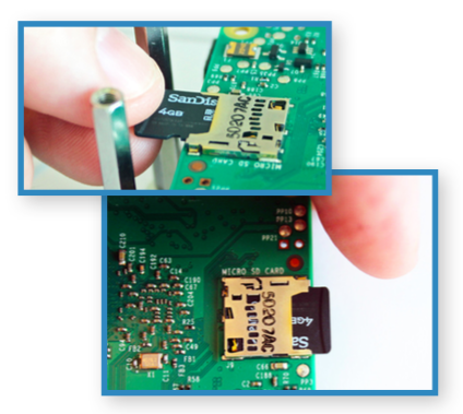
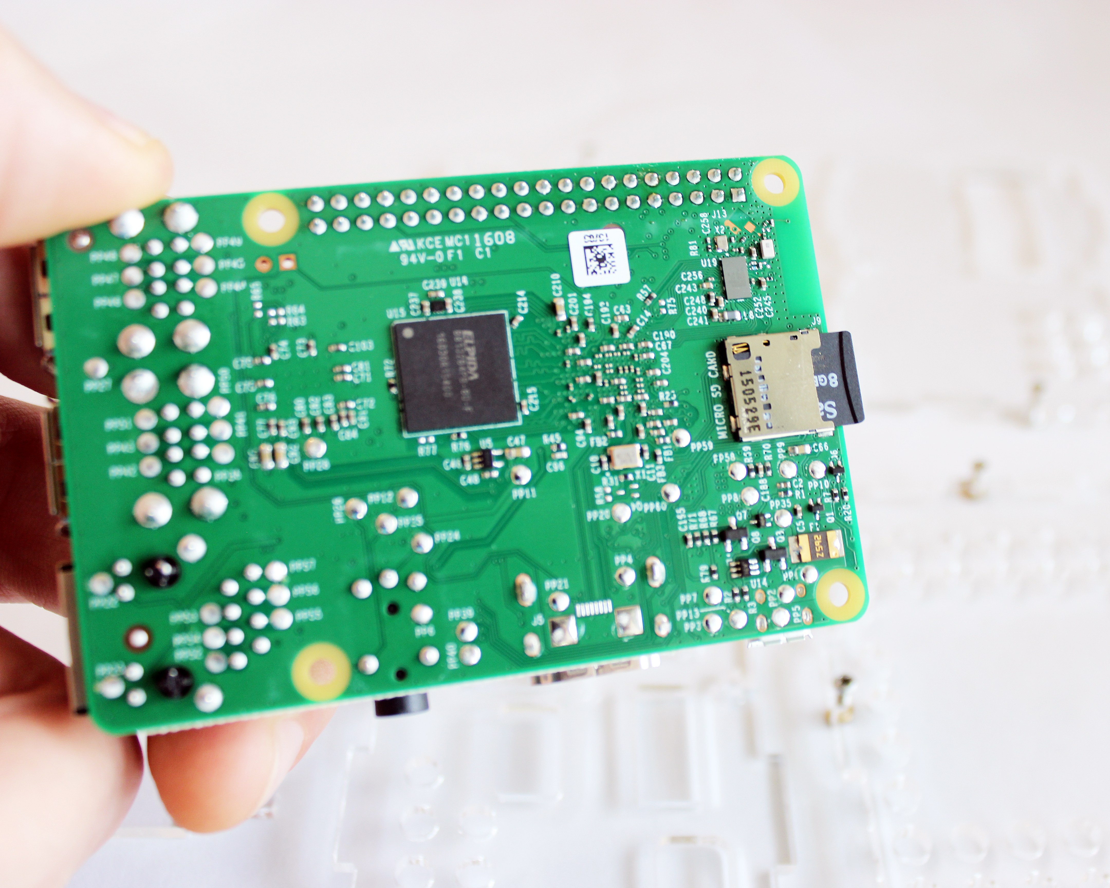
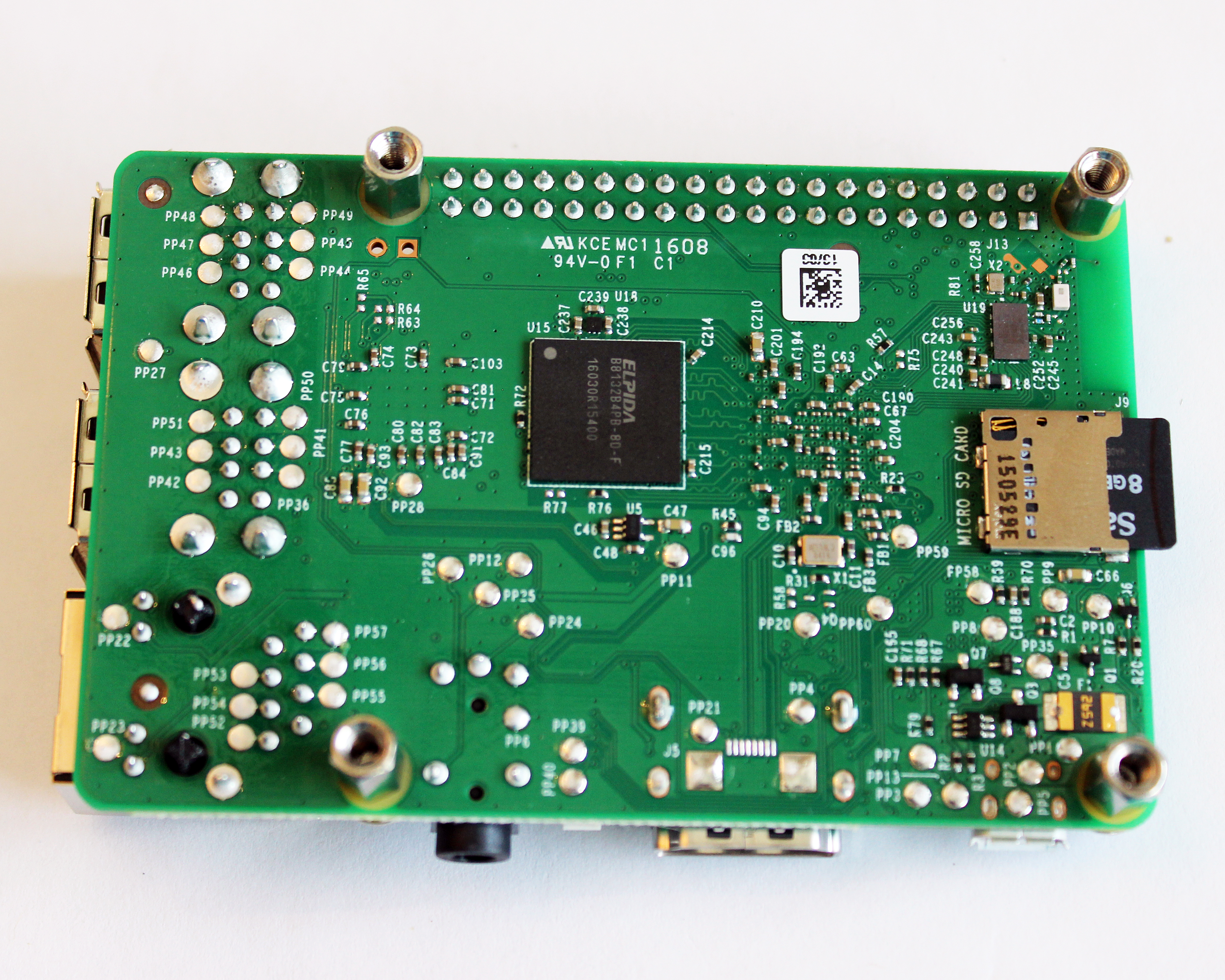
The SD Card is the hard drive of the BrickPi3 robot. We will insert it into the Raspberry Pi (the green board).
If you purchased an SD card from Dexter Industries it is either a standard Raspbian for Robots or CINCH, and the software is all set up on the card already, so just move on to “Inserting the SD card” below.
If you want to set up your own SD card click on one of the three options below. Note: If you have older software, we encourage you to upgrade for free or download our software here for free.
(Note: if you’re familiar with the Raspberry Pi and have your own SD card already, please note that a standard installation of Raspbian will not work without some modification; there are some modifications that must be made to operate the BrickPi3.)
Caution
A note of caution: never remove the SD card while the robot is powered on. The BrickPi3 case is designed to prevent the SD card from being knocked out. Removing or inserting the SD card while the BrickPi3 is powered can corrupt the SD Card.
Insert the SD Card into the Raspberry Pi
The SD Card from Dexter Industries may come packaged in a plastic jewel case. The microSD Card may come inserted in an SD Card adapter. If you think you may be missing your microSD card, check for it in the larger card and remove the microSD card from the adapter.
Download and use our software on your own SD Card:
If you want to download and use our modified Raspbian image on a dedicated SD card we have step by step instructions on installing the Raspbian for Robots Image to an SD Card here for both Mac and PC.
Our operating system comes with all of the software installed to get the BrickPi3 up and running, including the example programs.
You can expand the memory on your Dexter Industries SD Card from the desktop by clicking Menu > Preferences > Raspberry Pi Configuration > Expand Filesystem, or from the command line run this command:
sudo raspi-config
And choose “Expand the rootfs” to use all available space on the SD Card.
Note: Your username is “pi”, your password is “robots1234” and your hostname is “dex.local”.
Modify your own image:
If you want to use your own Raspbian installation, you must make changes yourself to the image. You can download and run our install script which will automatically download and install all the packages and dependencies required for BrickPi3 to your existing Raspberry Pi operating system.
Refer to the README here for proper instructions on installing BrickPi3 software to your own image.
Successful Bootup
This is a video of what a successful bootup with Raspbian for Robots and the Raspberry Pi looks like. Note that on the Raspberry Pi 3 the PWR and ACT LEDs are close to the micro USB power input, but they should perform the same.
2. Assemble the Case
A few notes before you begin:
You’ll need a small Phillips head screwdriver, preferably a jeweler’s size screwdriver.
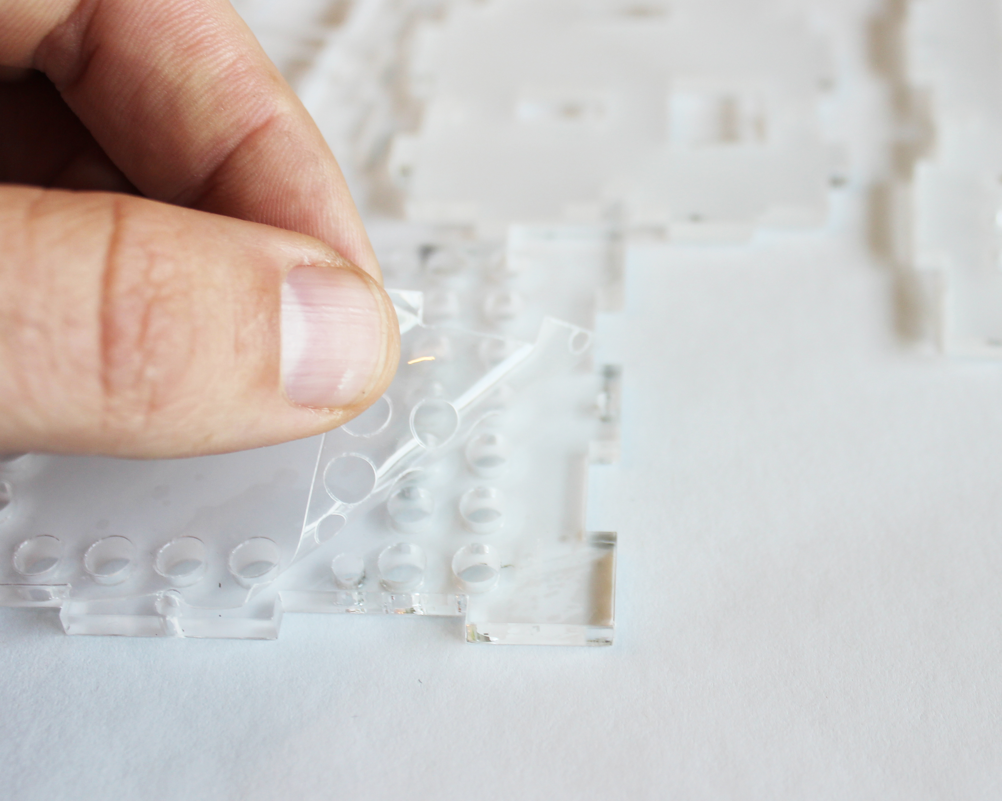
The acrylic case parts all come covered in protective wrap to protect it from scratching. You’ll first want to remove the wrap.
1). Unpack the parts from packaging.
You should have six acrylic pieces. Each piece will have numbers etched on them.
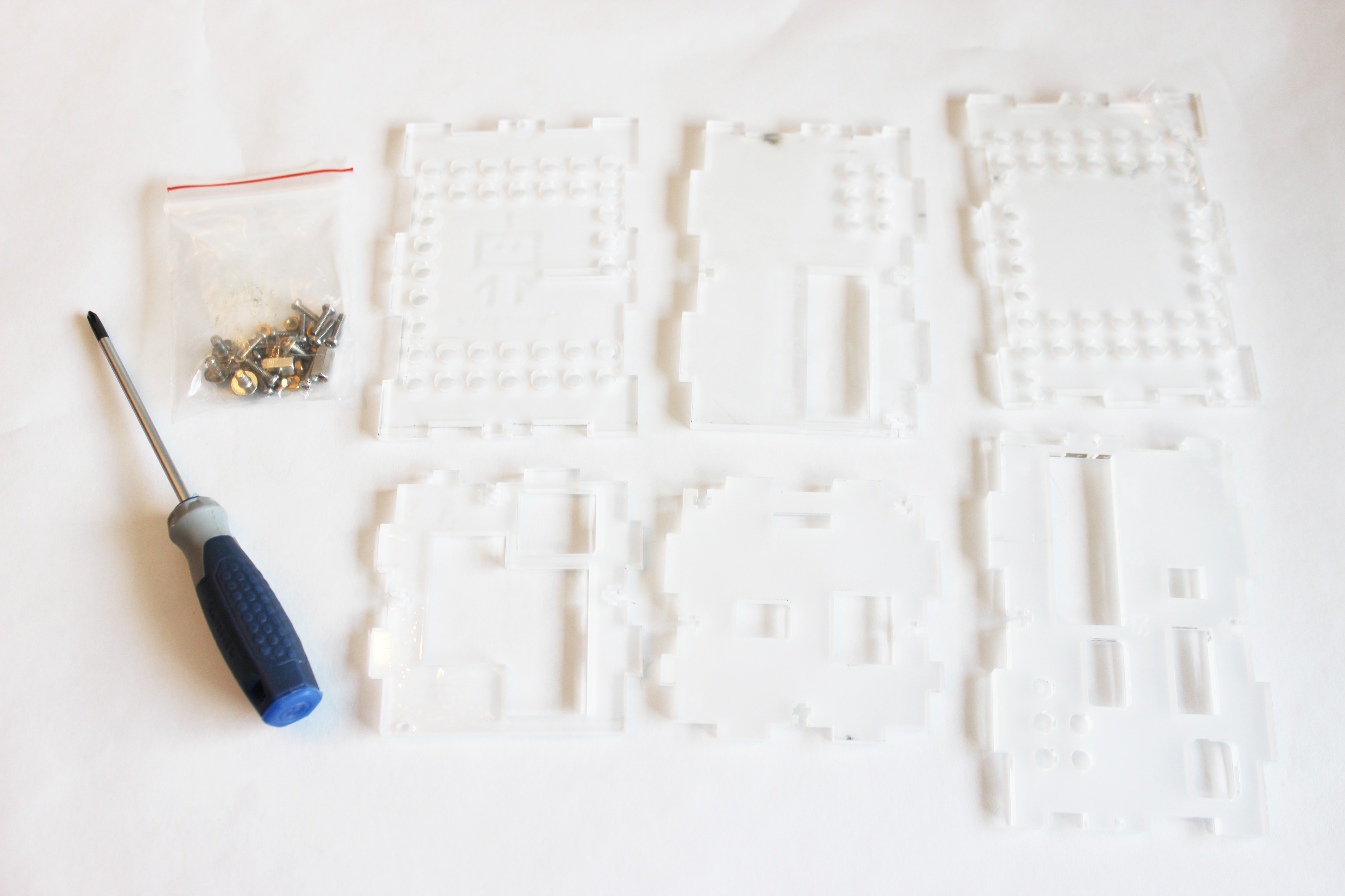
The contents include six pieces of acrylic and a bag of small screws and hardware.
2). Attach small screws to all Parts with small nuts.
On each of the six acrylic pieces you will see small holes. We will place the screws and nuts into these holes, and leaves the nuts loose.
The nuts should be going into the acrylic case. Turn the piece of acrylic so that you can read the text properly (if it is backwards it will appear mirrored). Next, place a screw through the acrylic, and place the nut on the screw. Screw the nut in only enough to hold onto the screw.
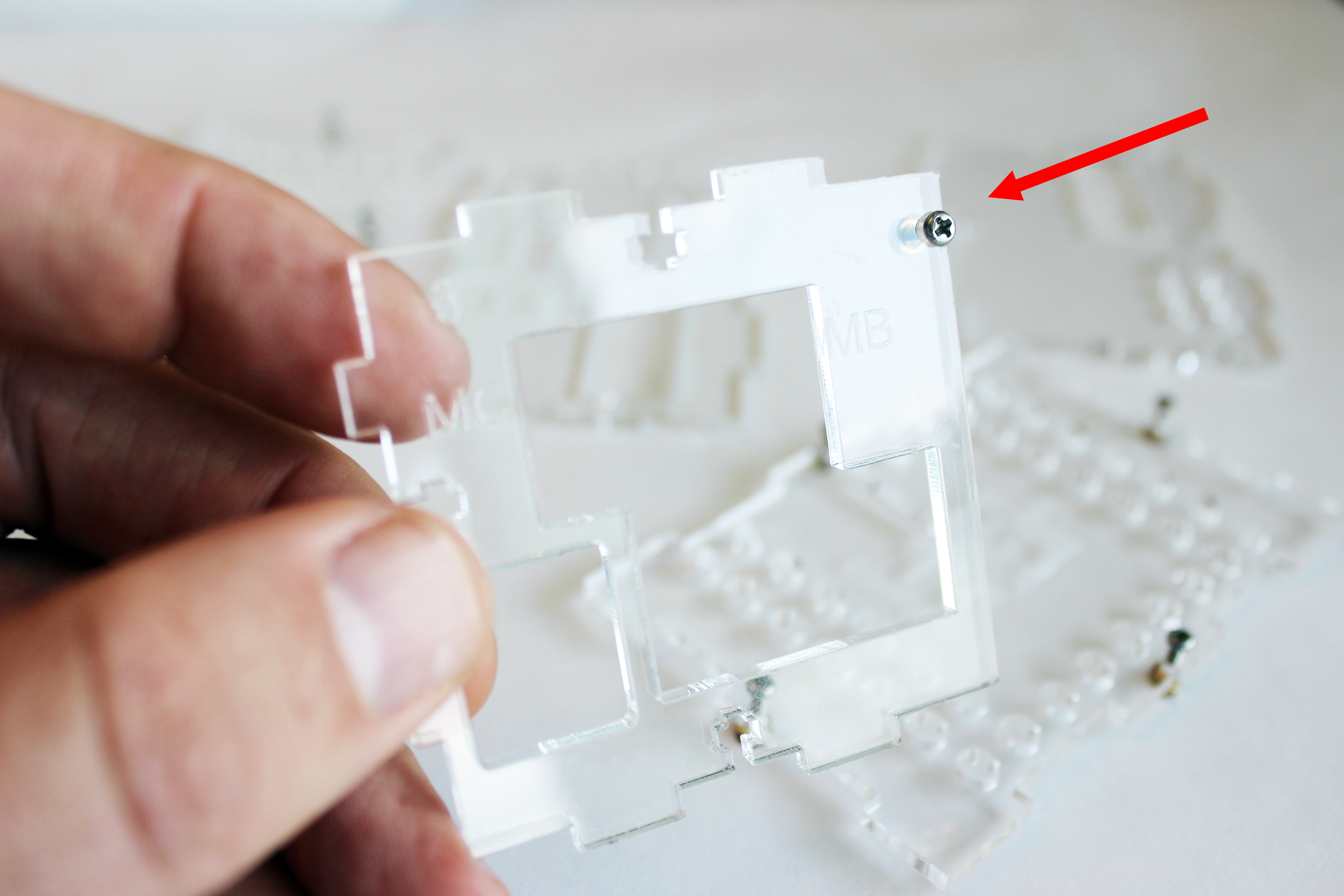
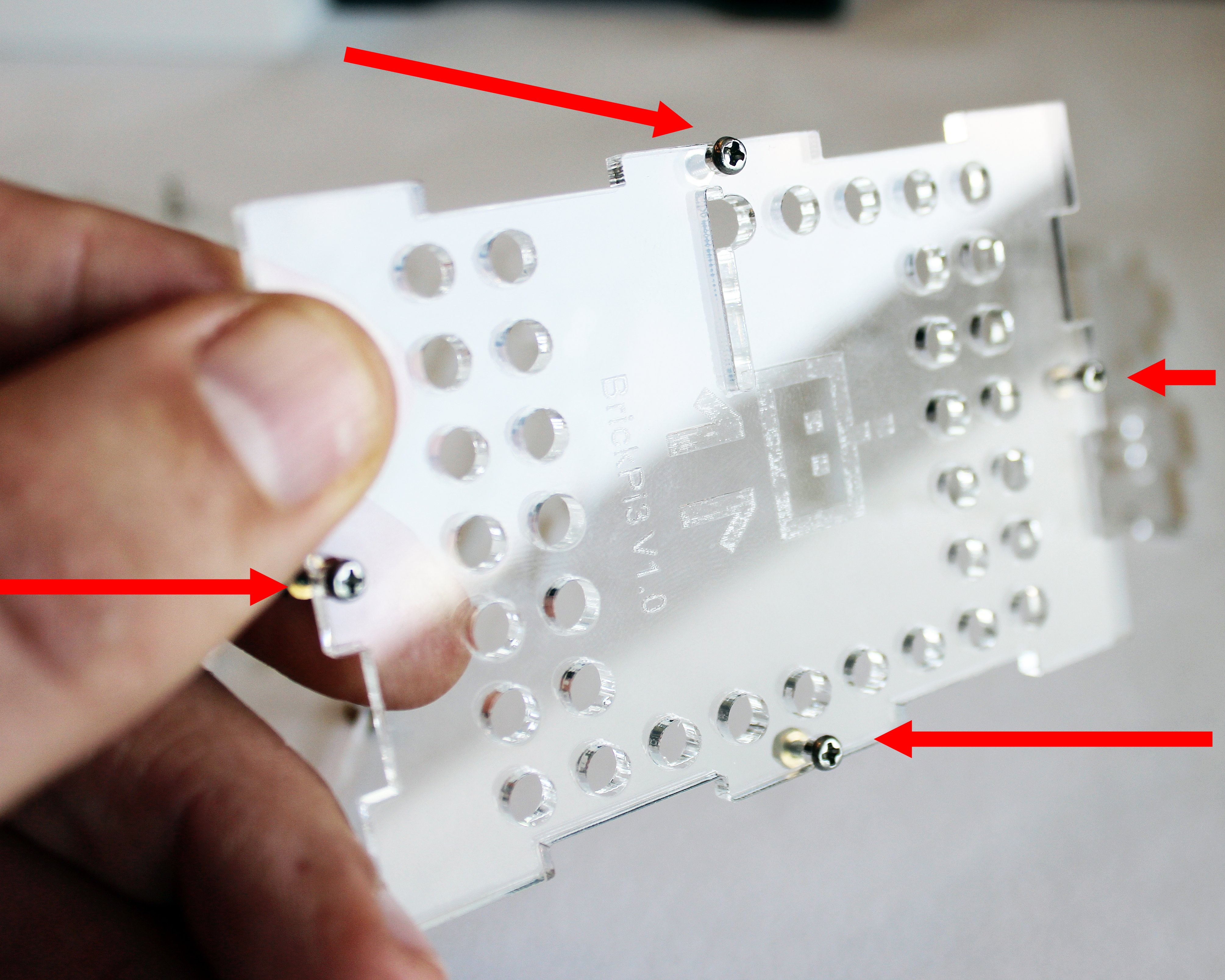
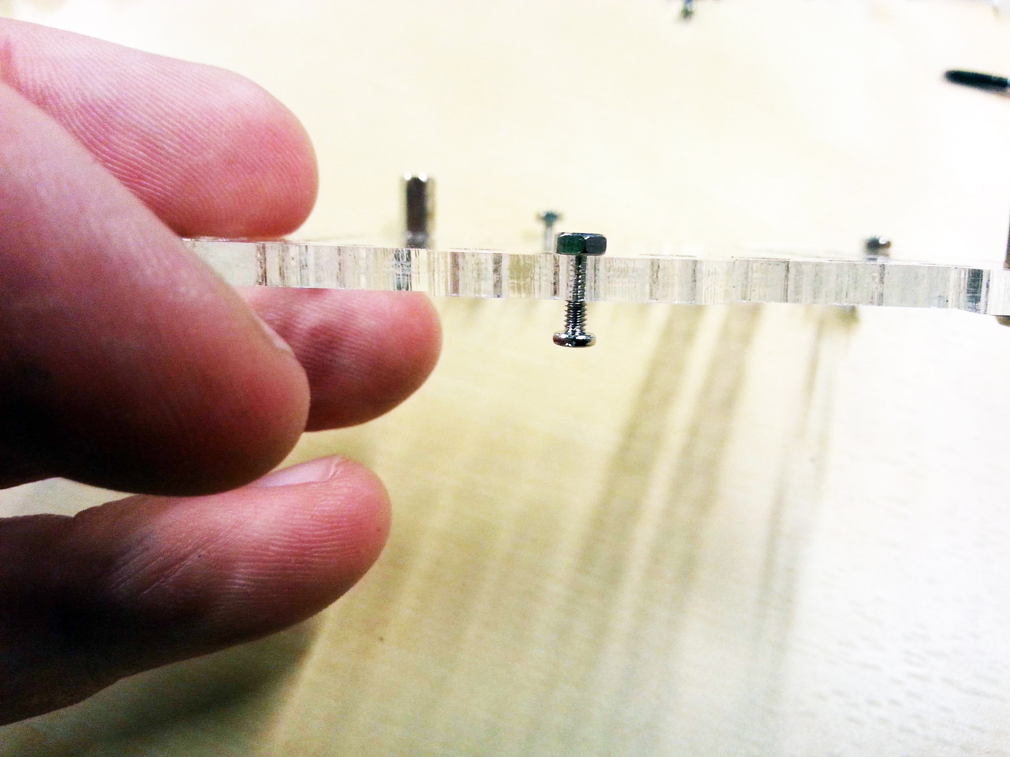
Screws are loosely attached.
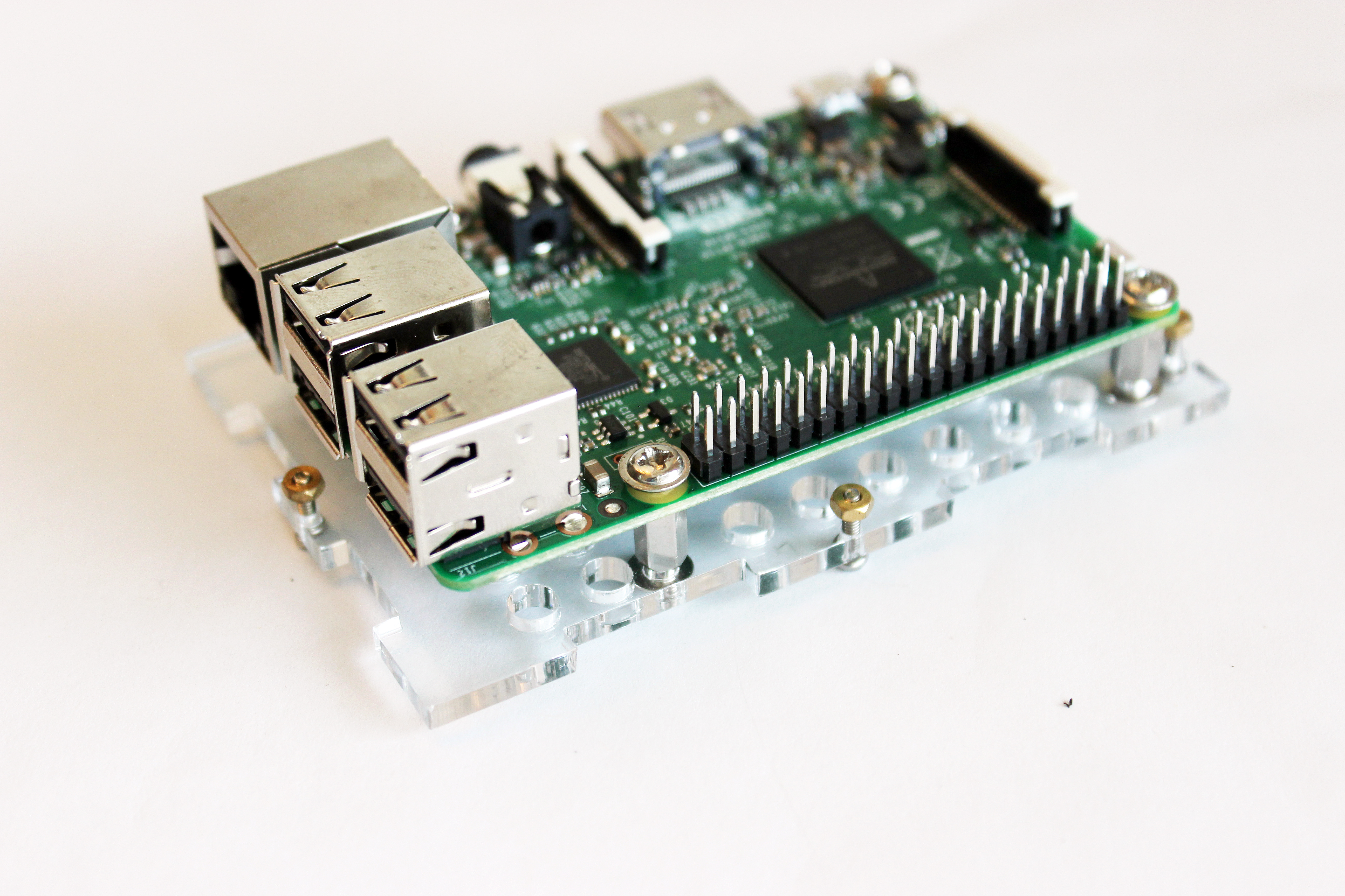
3). Attach the Raspberry Pi to the BrickPi3 Case.
In this step, we attach the Raspberry Pi to the BrickPi3 case to Acrylic Part 1.
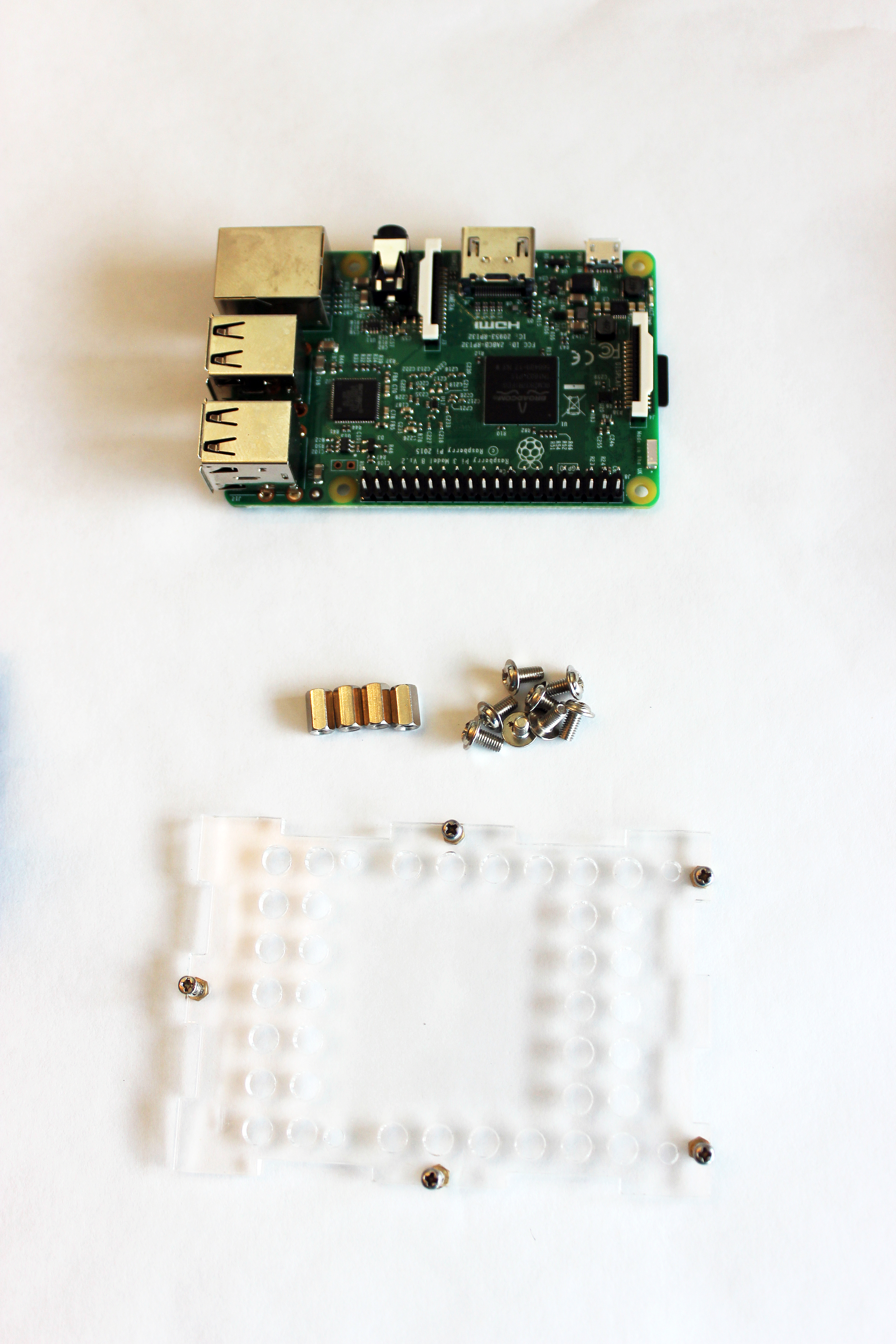 For this step, we’ll need the four short hex posts, along with 8 large screws.
We will first place screws through the four holes in the Raspberry Pi.
Find the four holes in the Raspberry Pi.
After the screws are placed through the board, attach the four hex spacers to the bottom of the Raspberry Pi.
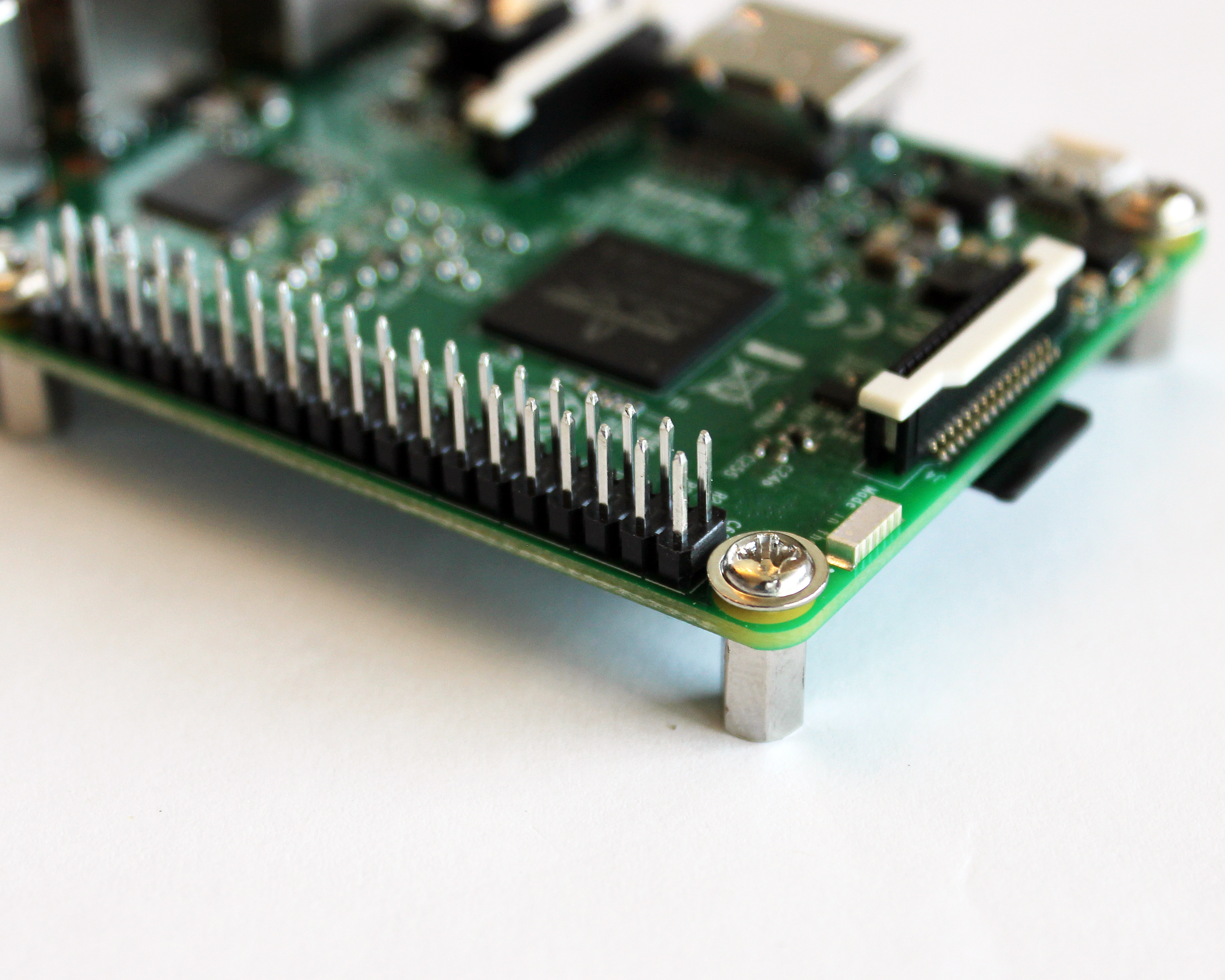
Finally, attach the Raspberry Pi to Acrylic Part 1. Note to get the orientation of the acrylic right: the nuts should be pointing towards the Raspberry Pi.
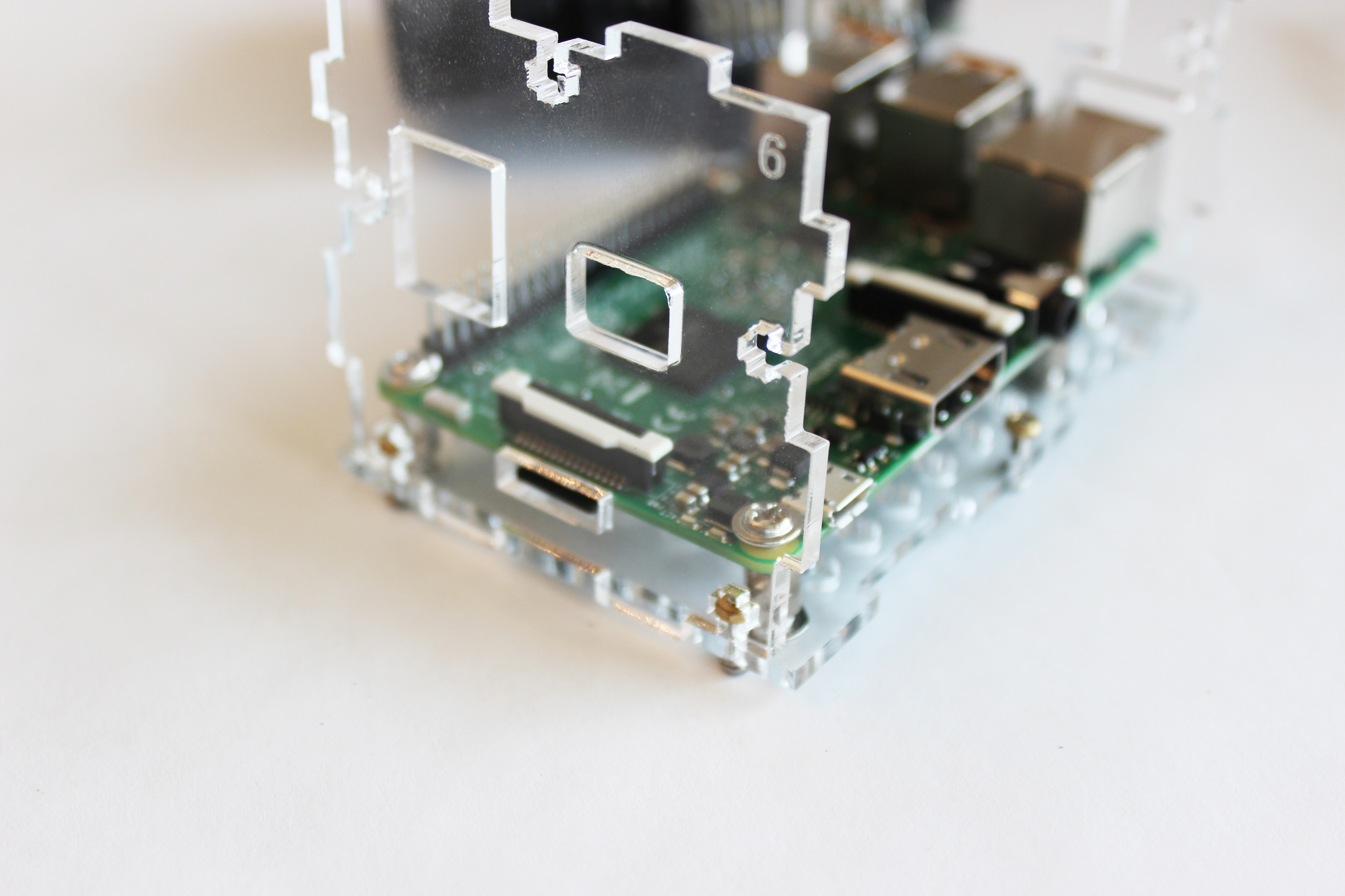
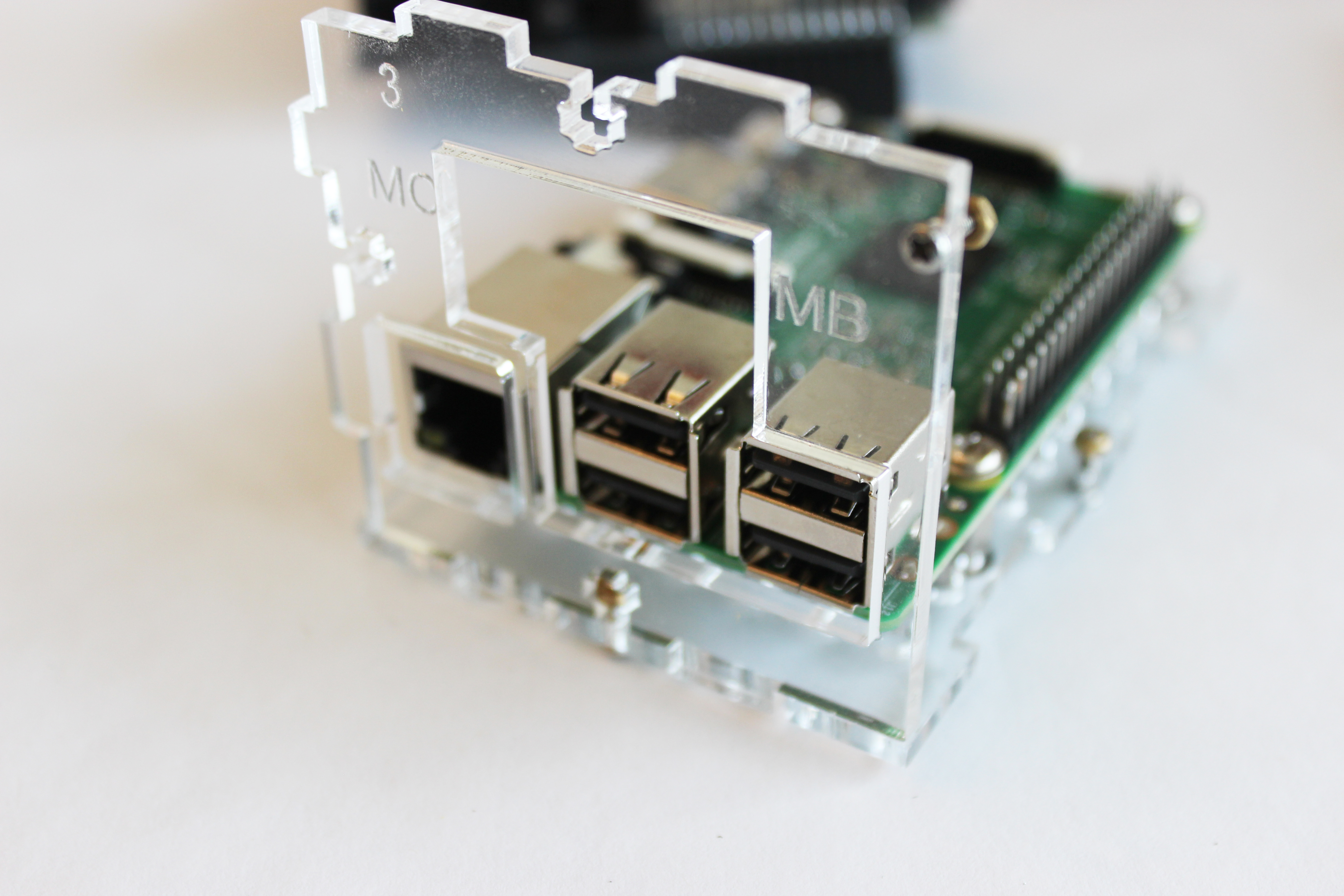
4). Slide Parts 3 and 6 onto Part 1.
Remember, the engraving goes on the inside! Leave the small screws loose at this point.
Leave the small screws loose at this point.
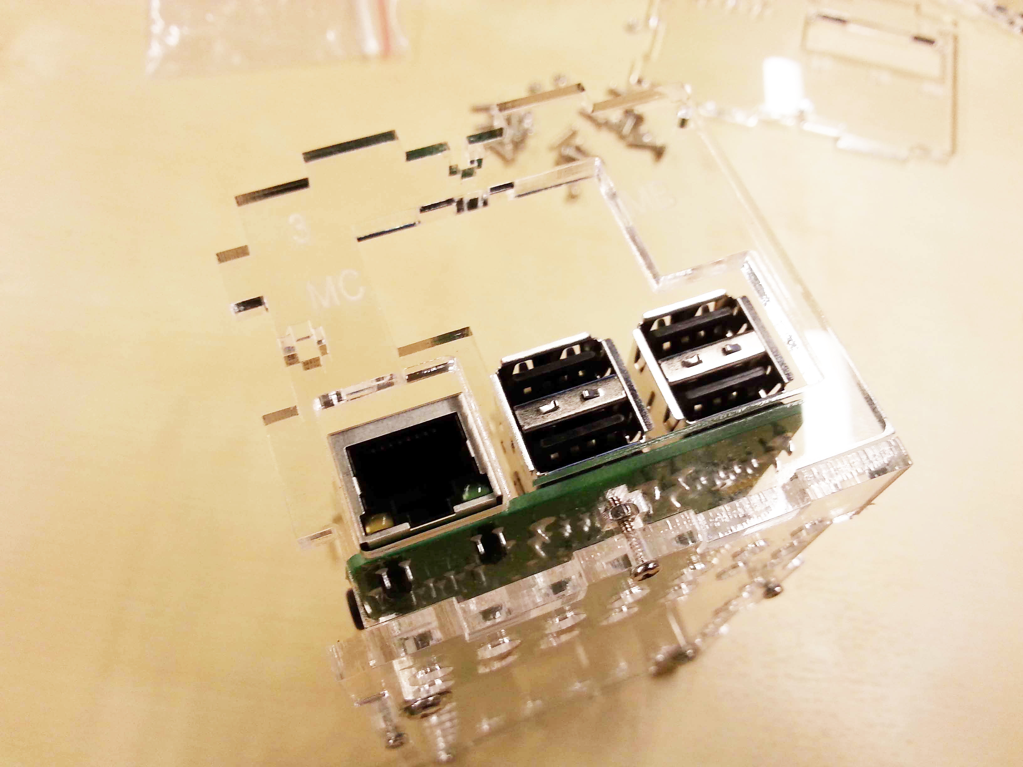
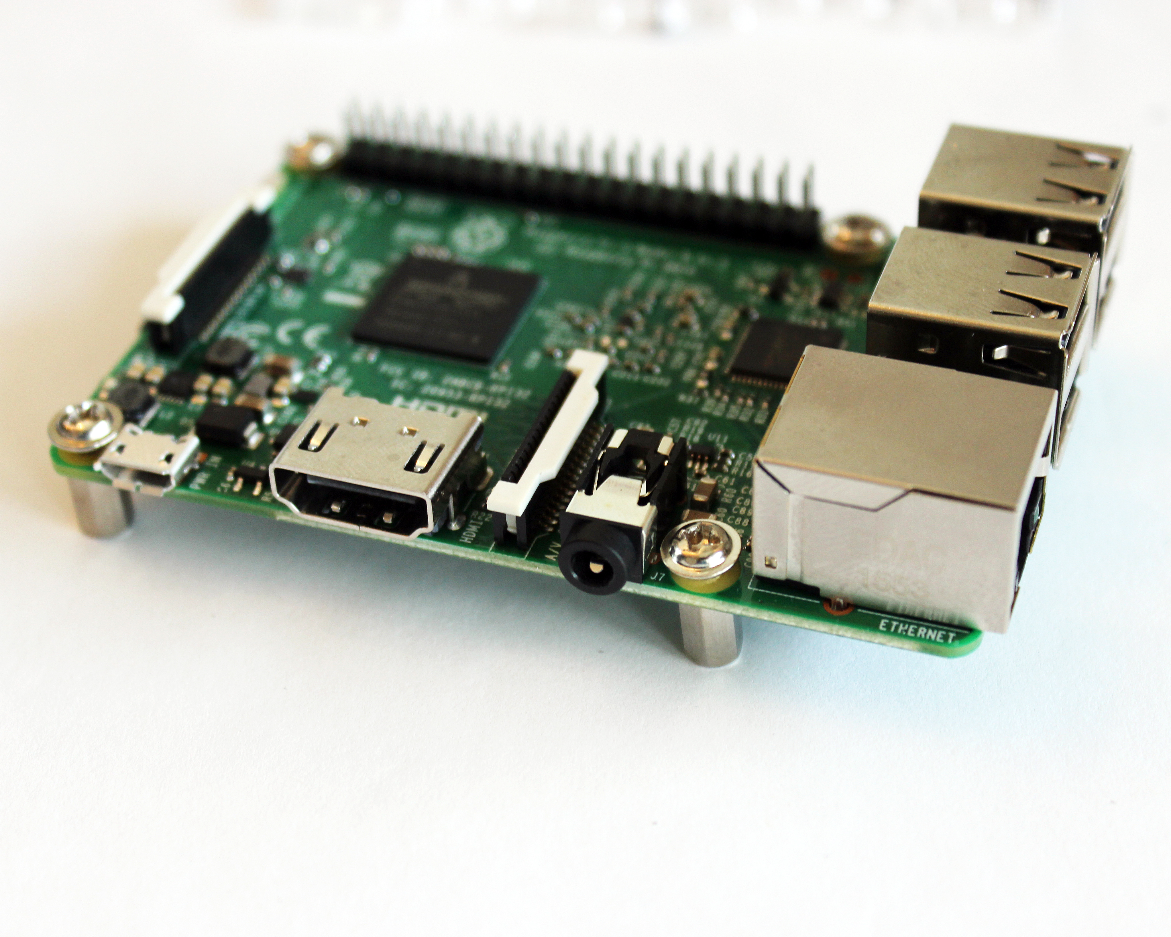
Attach end plates, and ensure that the USB and Ethernet ports align with their openings in the acrylic plate.
If you would like to connect a Raspberry Pi camera, now is the time to do so. The camera cable will need to go through the slot on case part number 5, but if the camera isn’t connected to the cable yet, you can slide the cable through when you attach part number 5.
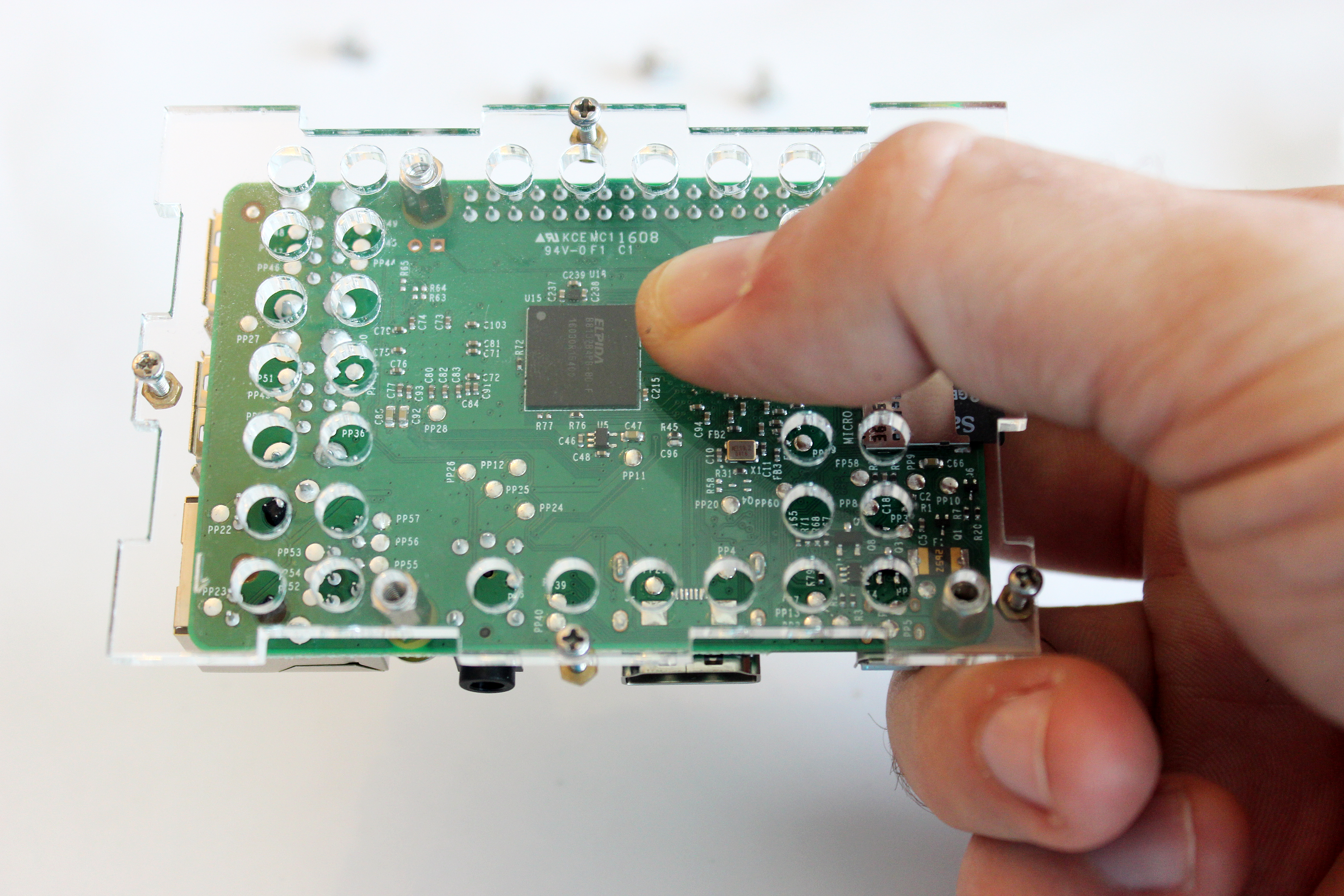
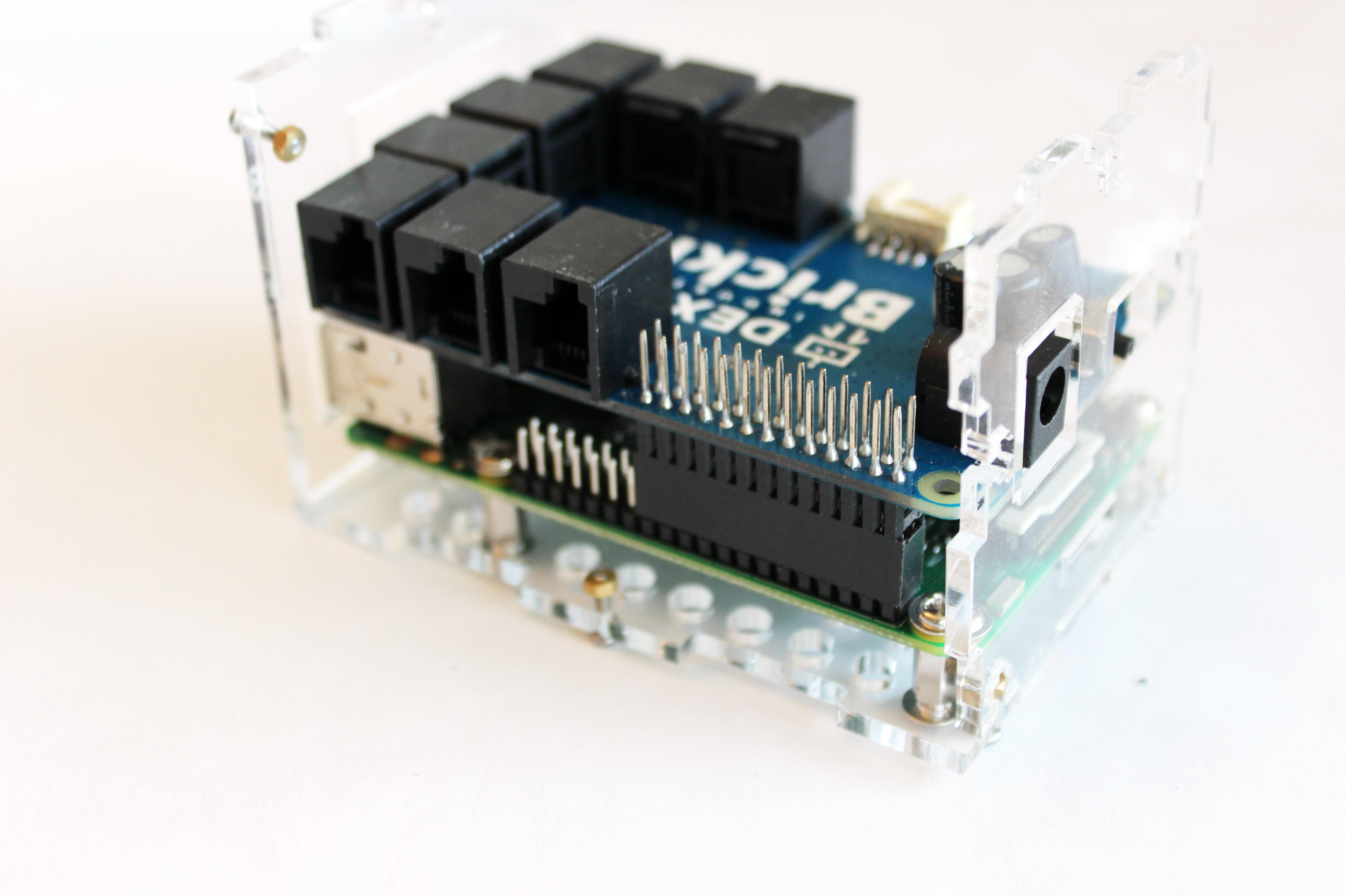
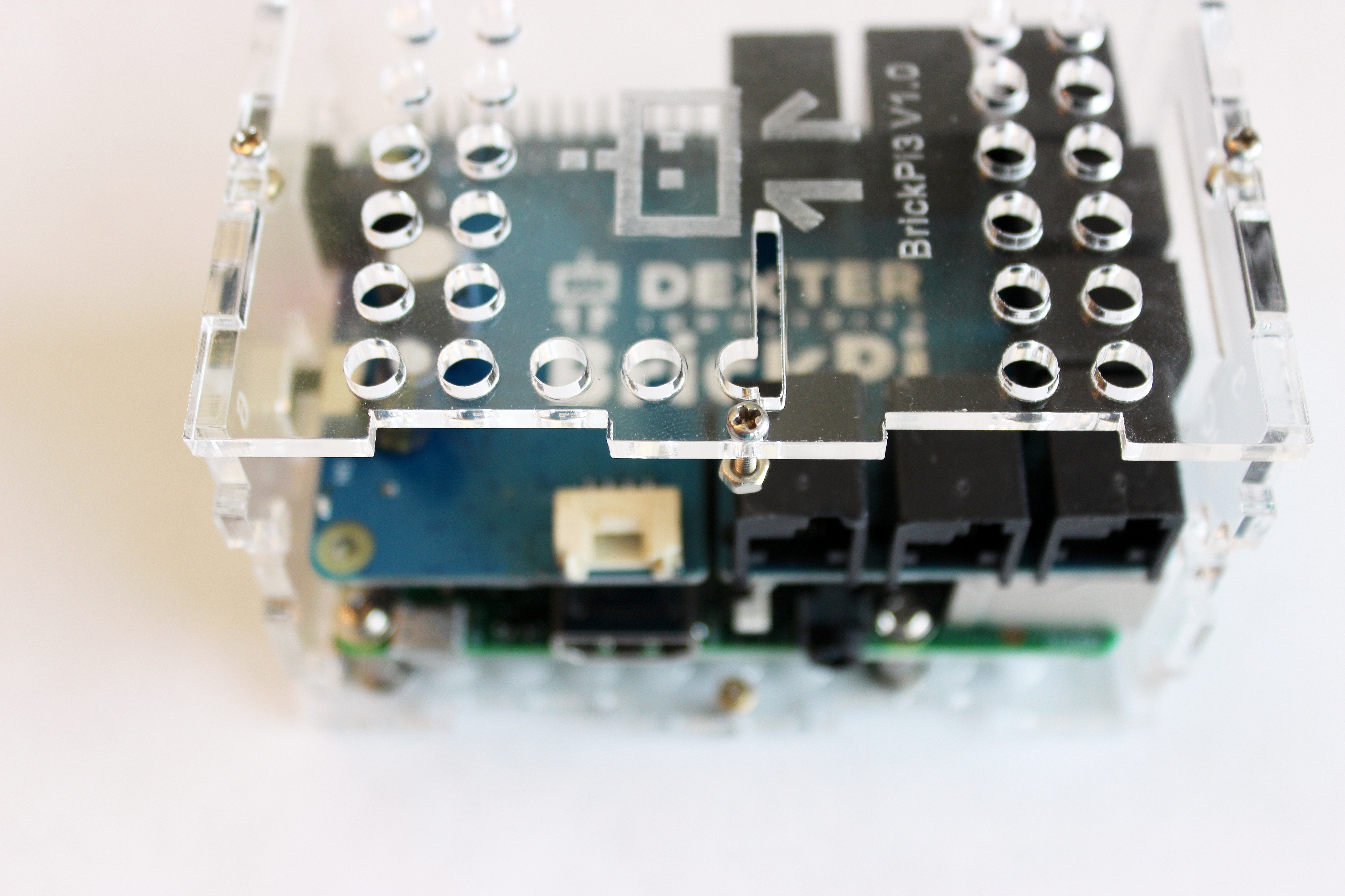
5). Next, attach the BrickPi3.
(this step is the perfect step to install the Pi Camera if you want to use one)
Prepare the BrickPi3 Board: Take the Protective Foam Off the Pins
Be sure to take the foam off of the pins on the BrickPi3. The BrickPi3 is shipped with foam on the GPIO pins to prevent them from being bent. Be sure to remove the foam before proceeding to use your BrickPi3!
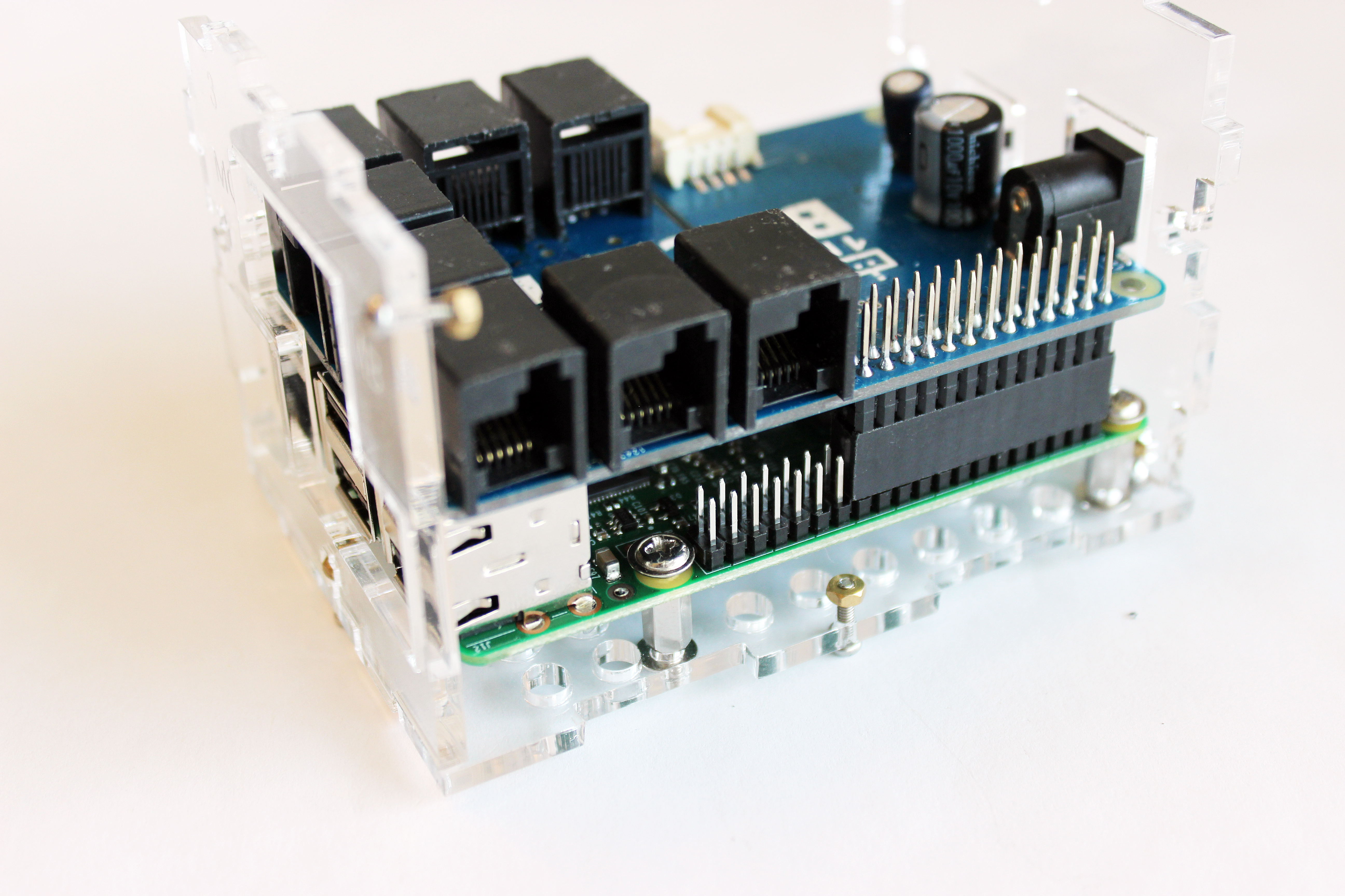
Attach the BrickPi3 board to the Raspberry Pi.
6). Attach the top plate to the case.
Leave the screws loose at this point. Attach the top plate, Part 5 (this part should have Dex engraved it). Align the slot for the camera ribbon cable over the slot in the BrickPi3 board for the camera ribbon cable. Be sure to leave the screws loose at this point.
Attach the top plate, Part 5. Be sure to leave the screws loose at this point.
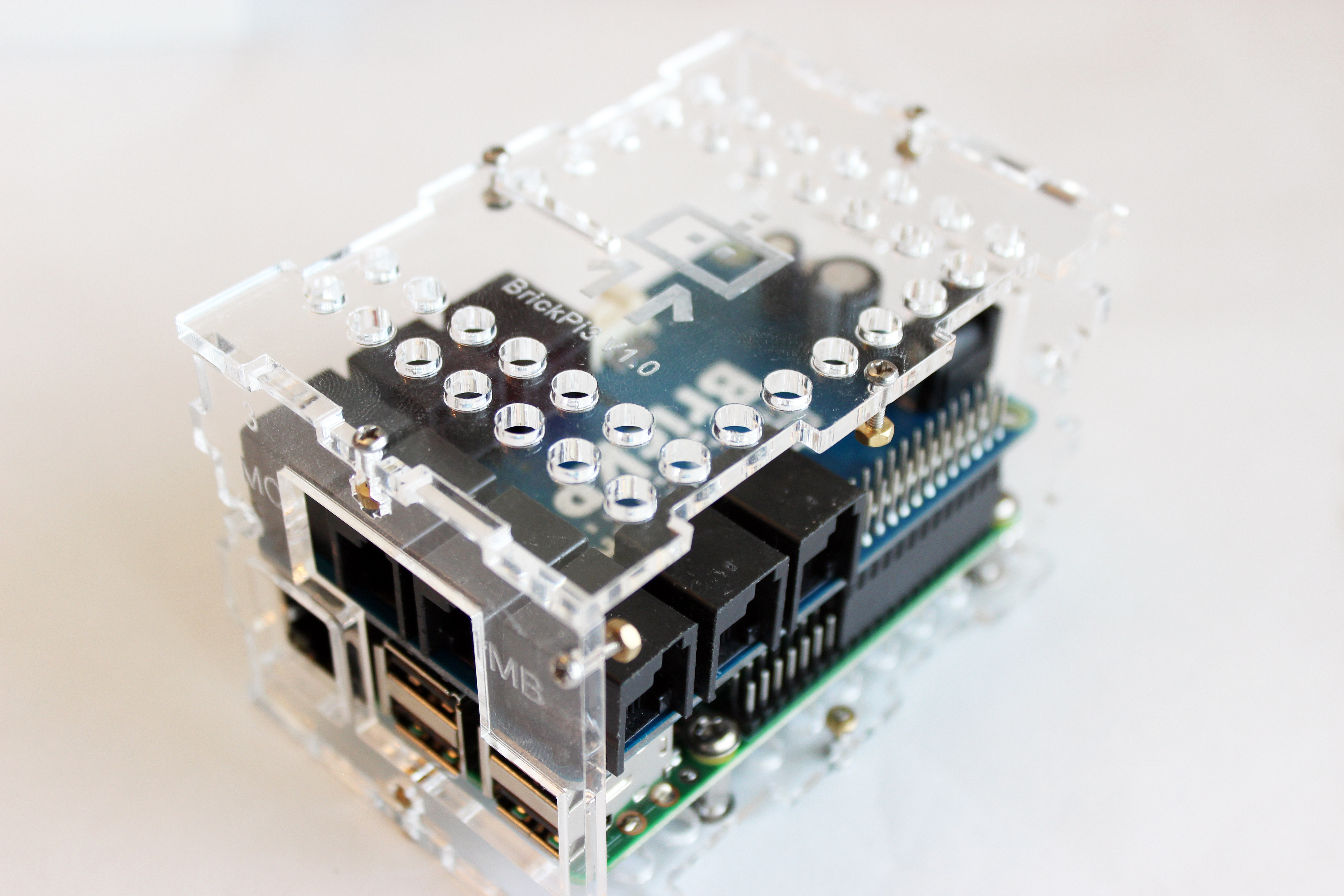
Align the slot for the camera ribbon cable over the slot in the BrickPi3 board for the camera ribbon cable.
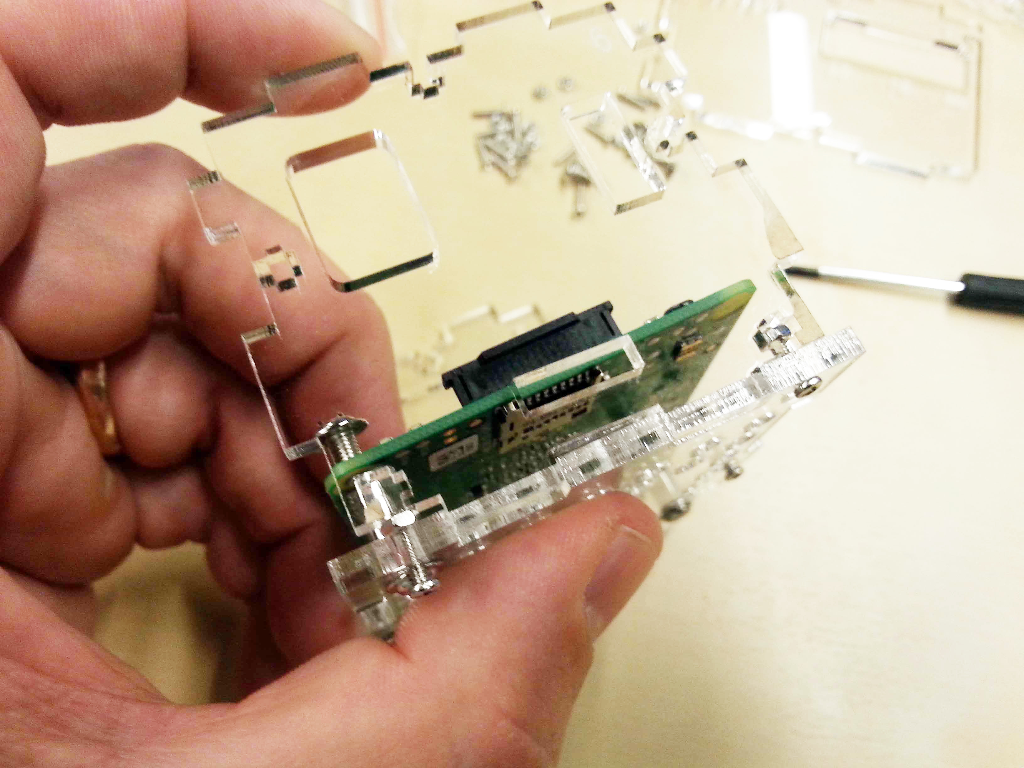
7). Slide on Parts 2 and 4
Finally, slide the side panels on. These will cover the sensor ports.
The completed case!
8). Tighten the smalls screws.
With all acrylic parts attached, and the full BrickPi3 Case Assembled, tighten the small screws around the case.
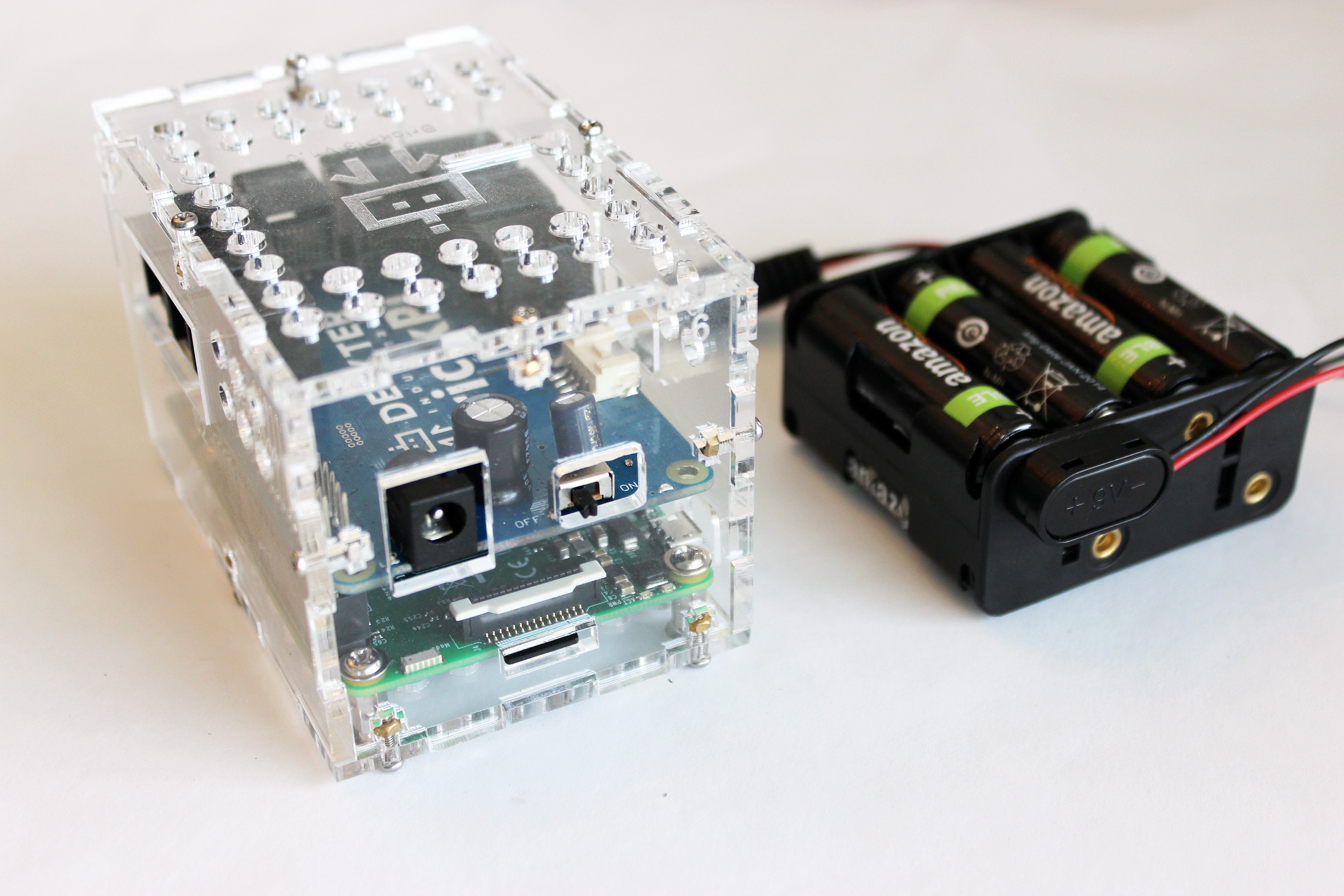
3. Power Up!
Now that we have the SD card inserted and the BrickPi3 Case assembled, we can move on to powering the BrickPi3.
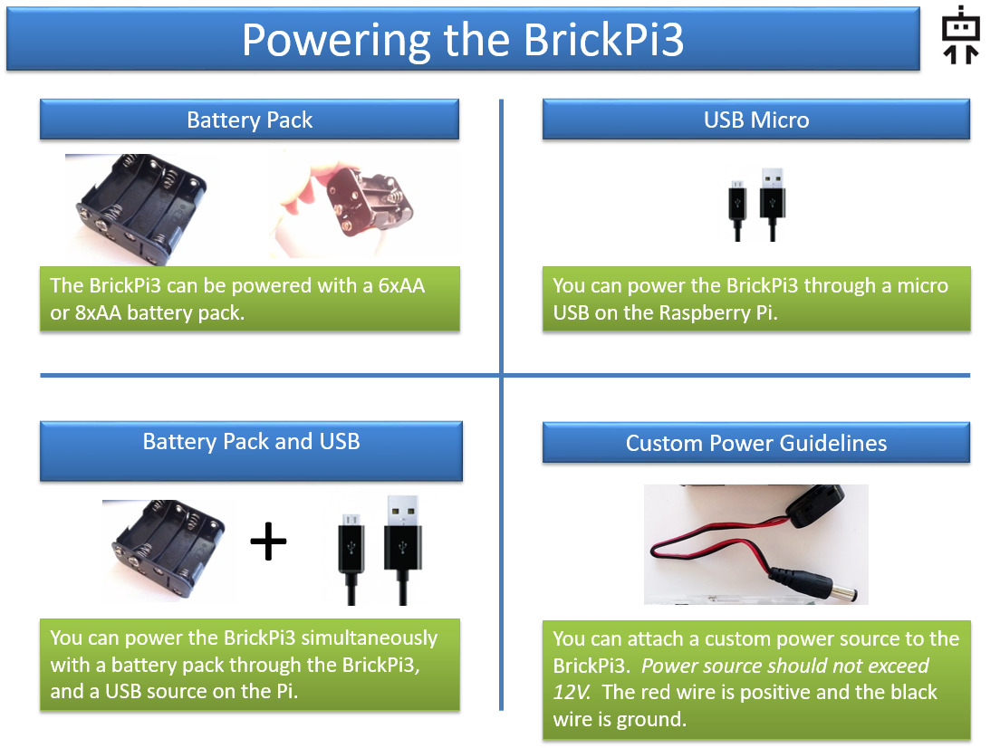
Below, you’ll see the 9V adapter, the BrickPi3, and the Battery Pack. We recommend using an 8XAA battery pack (as shown in the picture), which comes with the BrickPi3 Base Kit and Starter Kit. You can extend your battery life by running the Raspberry Pi and BrickPi3 from the Raspberry Pi Power Supply while programming. However, never run the motors when the wall power supply is pulled in.
A Note of Caution: Before powering your BrickPi3, make sure the SD Card is properly inserted into your Raspberry Pi. If you insert the SD card after starting the Pi, it can corrupt and damage the SD Card.
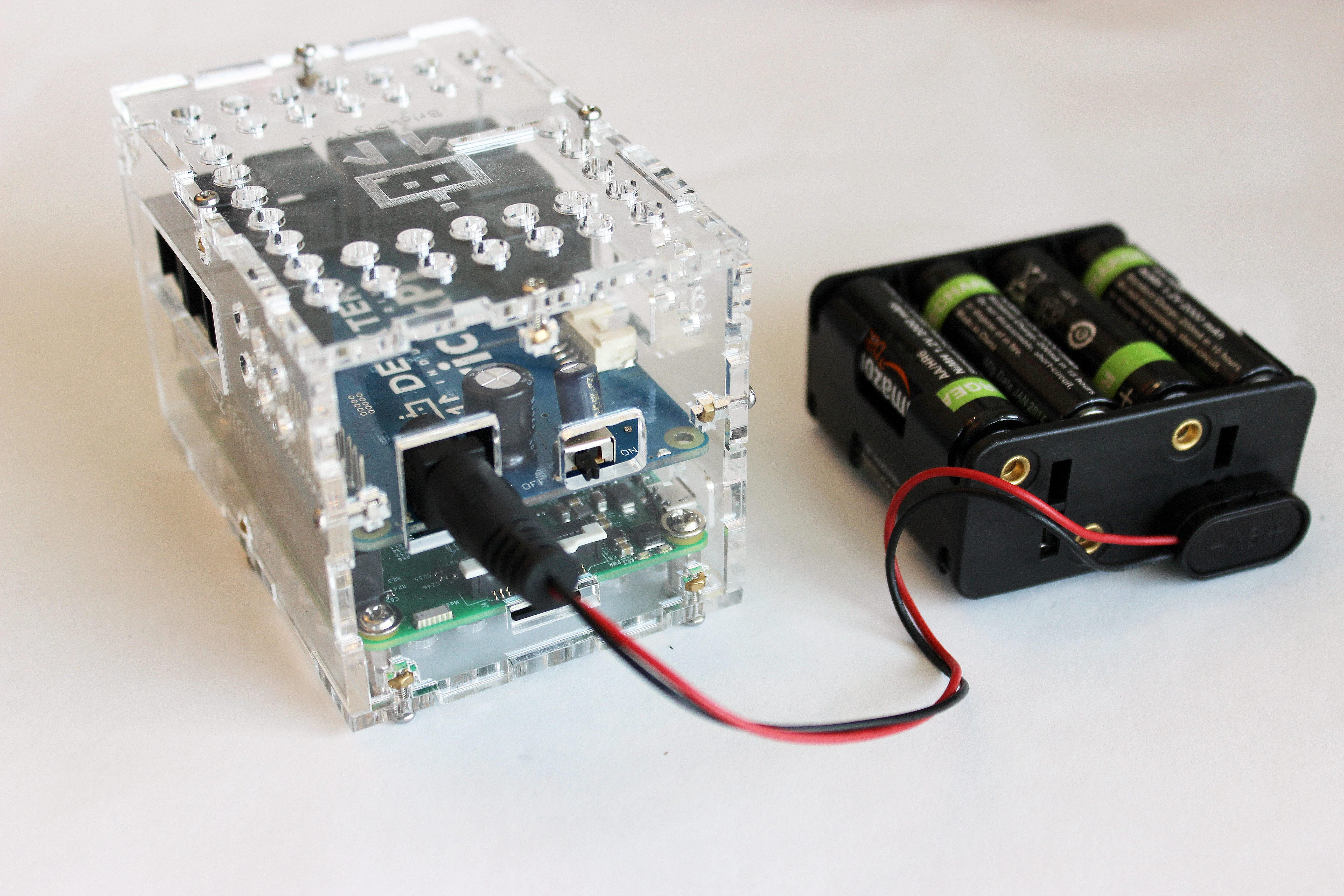
1). First, turn the Power Switch to Off. Turn the power switch to off on the BrickPi3 board before powering the BrickPi3. It is next to the power jack.
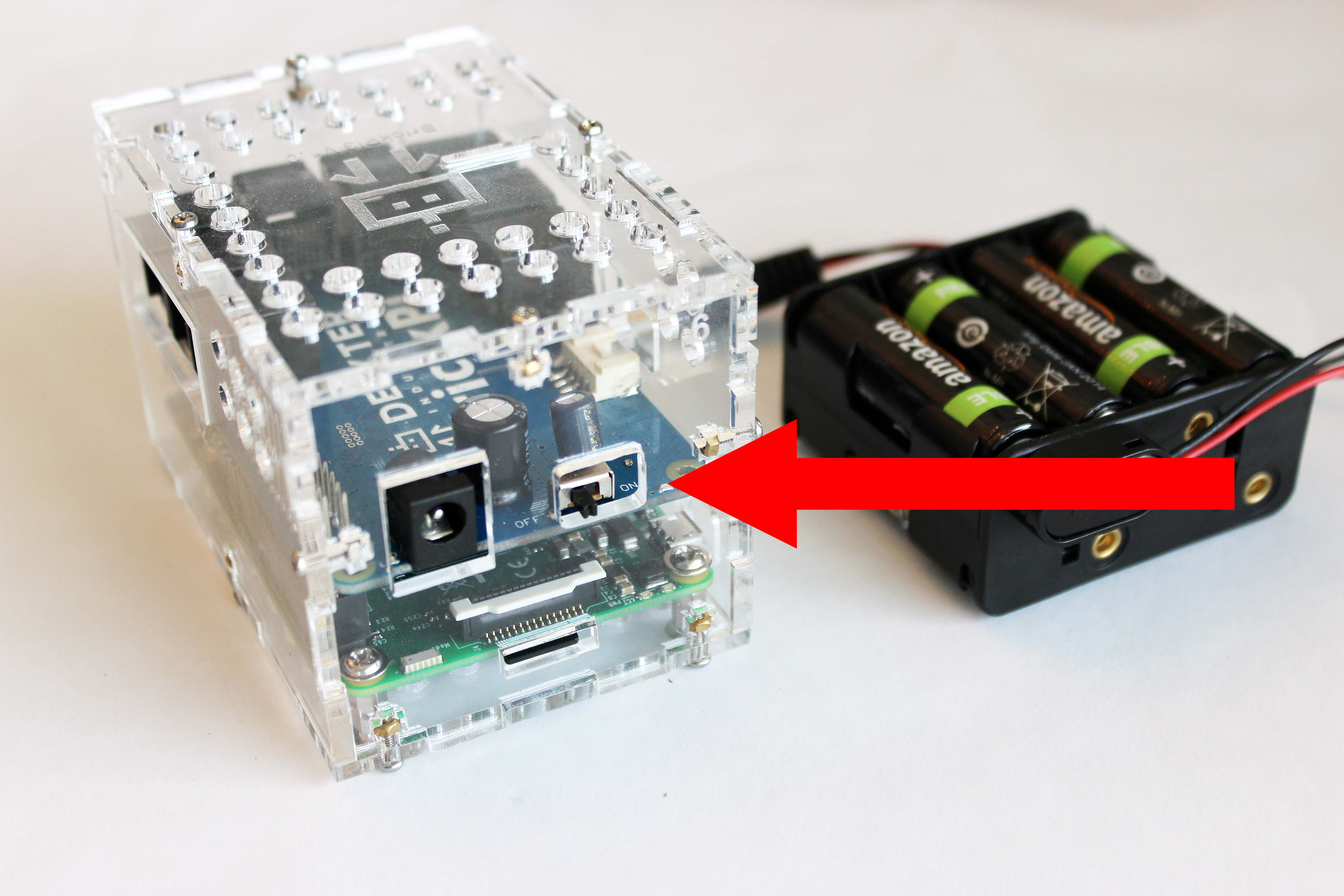
2). Next, find the Power Connector on the BrickPi3. You can see the power connector, which is black plastic, above the SD Card slot on the Raspberry Pi. It is a round barrel-shaped power jack.
3). Slide the Barrel Jack into the Black Plastic Female Barrel Jack on the Raspberry Pi. Now the battery pack should be full connected to the BrickPi.
4). Turn the power on. Turn the power switch to On. You should see the BrickPi3 turn on. Note the red LED is glowing on the Raspberry Pi, indicating that power is on.
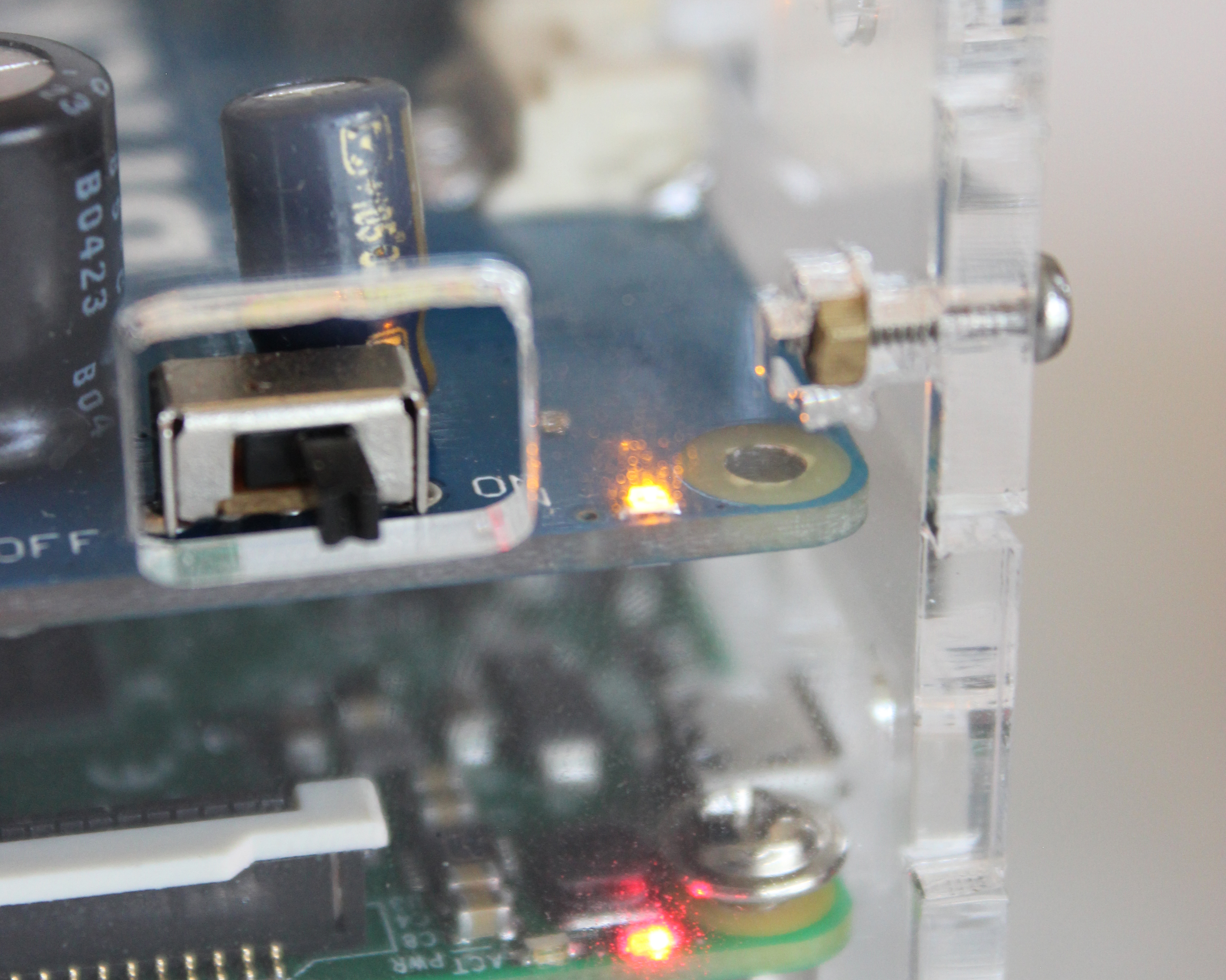
The BrickPi3 Power Switch On and Power LED On.
More Information on Power
If the green LED is off, then the BrickPi3 is not getting power. If the yellow LED is flashing 4 times per second, the voltage is too low to run the motors. If the red (power) LED on the RPi is off, the RPi is not getting adequate power.
To keep the Raspberry Pi from crashing, the motors will automatically be disabled if:
– the battery voltage drops below 6v OR
– the battery voltage drops below 6.8v and the Raspberry Pi voltage drops below 4.85v.
The motors will automatically resume when the voltage becomes adequate.
Other than running motors, the entire BrickPi3 can be powered and run normally off of 5v through the Raspberry Pi USB-Micro 5v power input.

Infographic: Power Options For Your BrickPi3 LEGO Robot
Infographic: Powering the BrickPi3
Questions? Ask on the BrickPi forum here.