In this HowTo, we’ll show you how to get your EV3 and your Arduino to communicate, and how to use Arduino Shields with the EV3. The EV3 is much more powerful than the NXT, but at the time of writing this article, the software available is much harder to hack with. We recently tried to make this easier by developing EV3 blocks for I2C communications. In this post we’ll show you how to use the EV3 blocks to communicate with the Arduino and any shields you may want to add to the EV3.
We use a breadboard to break out the I2C lines in this example. You can use the NXT Breadboard adapter to break out the Mindstorms sensor cable to use the NXT cable directly without messing up the cables. You can order them on our website here, and on Amazon here.
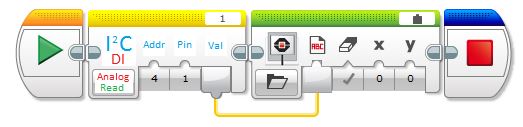
In this tutorial, we’ll use the Arduino Uno to read and write data to the LEGO Mindstorms EV3. We’ll also demonstrate how to use the Arduino to read an analog values and send them to to the EV3. You can easily modify this to send or receive any kind of data to the EV3, from accelerometer readings to geiger counter values. This is probably the fastest way to add your own sensors and devices: when you connect the EV3 and the Arduino and the world is yours!
The EV3 and the Arduino can be made to talk over I2C. In this tutorial, we setup the Arduino as an I2C slave, and the EV3 as an I2C master.
In this example, we show you how to send commands to the Arduino from the EV3 and how to write a program that requests data from the Arduino.
Background
I2C is called a “two wire interface”, because it uses two wires to communicate. One  wire provides a clock: this makes sure that both devices are sending information at the same speed. The clock line is usually referred to as “SCL“. The other wire is for sending data (data is sent and received by both devices at the same time), and is usually referred to as “SDA“. The master (always the EV3) always controls the communications, and always sets the communications clock for both devices. The device being controlled is referred to as the slave. When the master sends a command, the slave drops everything and listens. When the master demands information, the slave provides that information.
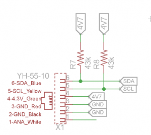
In this example, we did not have to use pullup resistors on the I2C lines. However if the I2C is not working at all, you might have to use 47k pullup resistors on the SDA and SCL line to pull the I2C to 4.7V on the VCC line.
Setting up the hardware
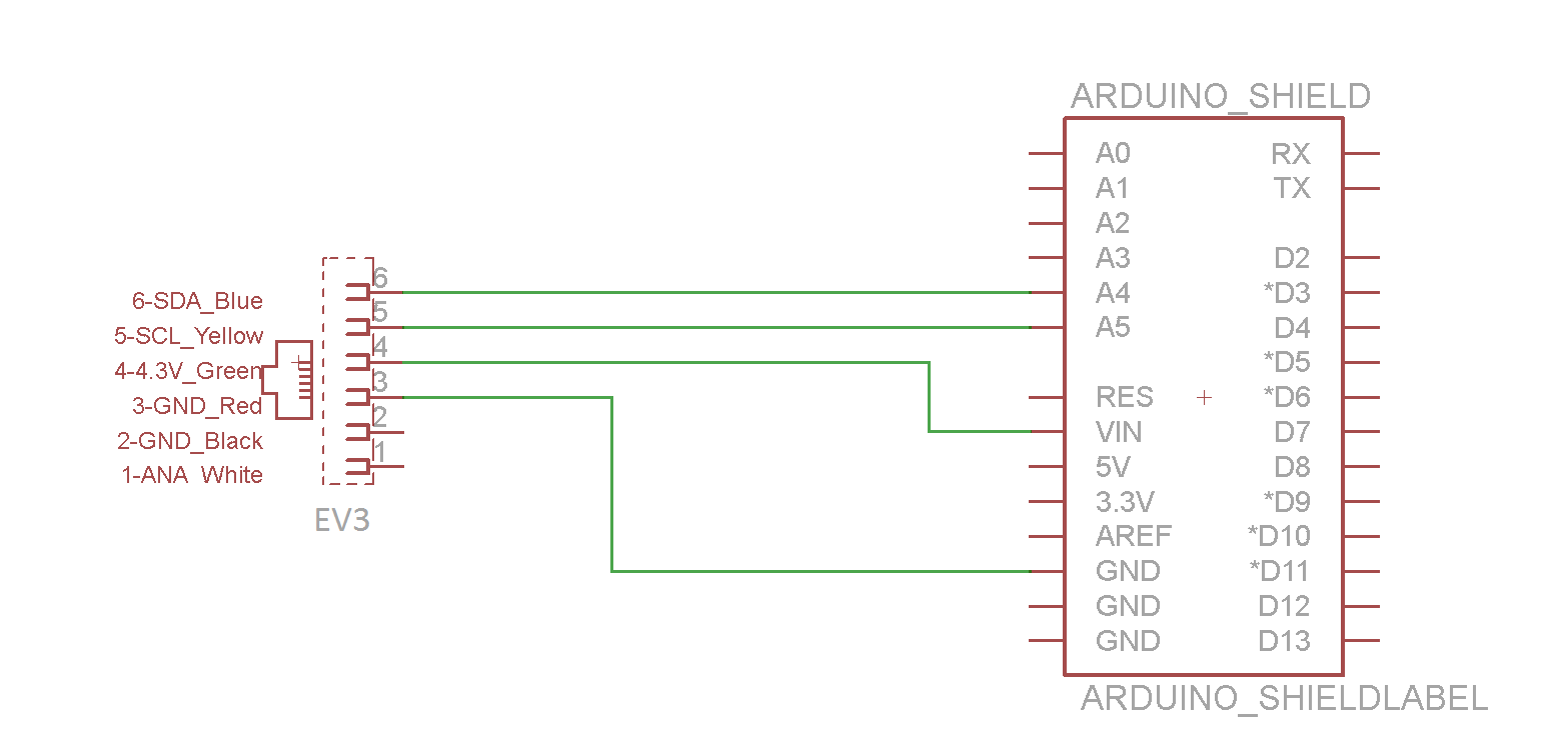
First, a schematic of what we’re aiming for. The schematic shows the EV3 plug on the left hand side of the drawing, and the Arduino on the right hand side. We will need the Ground, VCC, SDA and SCL to be connected.
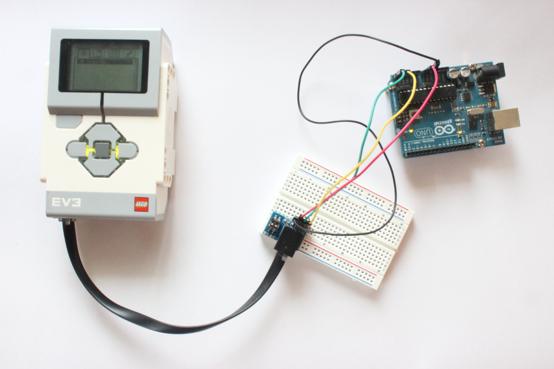
For the setup, we’ll wire together will look like this: Ev3–> Breadboard –>Arduino. You can see an overarching view of everything below.
In this example, we’re going to connect only the SDA, SCL lines (for communications), VCC for powering the Arduino from the EV3 and the ground (GND) line to equalize the communication voltages.
Connecting to the Arduino:
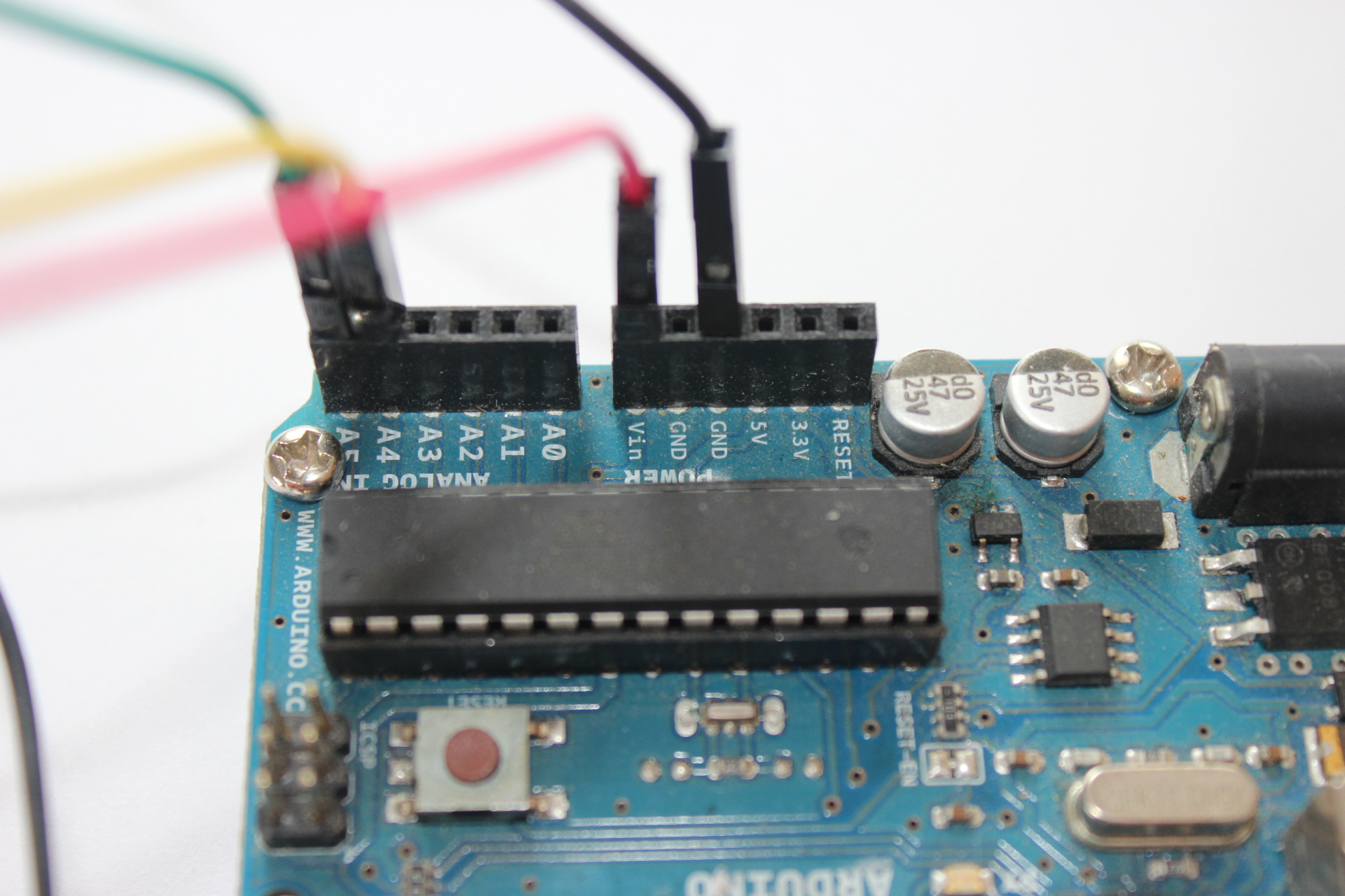
First, place on jumper into a GND port on the Arduino. Place one jumper on A5 (SCL, the clock line) of the Arduino Uno, and one jumper on A4 (SDA, the data line). In the picture, you can see that we placed the Red jumper to VCC, Black jumper into GND, the Yellow Jumper into SDA (A4) and the Green jumper into SCL (A5).
Connecting to the EV3:
The easiest way to connect this up to the EV3 is to use the Breadboard adapter . Again, same colors go in the same spots: the Yellow wire in our example, is connected to SDA on the breadboard. Ditto for SCL and GND and VCC.
Just to clarify: SDA –> SDA ; SCL –> SCL.
You can hack together a custom adapter pretty easily: cut off one end of the standard EV3 black cord, and open up the wires. SDA and SCL are yellow and blue, while the gnd line is black and the red and the VCC is the green one.

In these pictures, the following colors correspond to these lines:
- Black: Ground
- Red: VCC
- Green: SCL
- Yellow: SDA
On the Arduino Side, we will connect the SDA, SCL, VCC and Ground into the Arduino headers.
Software:
The software for the EV3-Arduino interfacing is divided into two parts. One is the Arduino sketch that goes on into the Arduino and the other is the LEGO MINDSTORMS EV3 Labview software on which the blocks are created which send and receive the data to and from the Arduino.
All the code can be downloaded and used from our Github EV3 repository.
Setting the Arduino up for I2C: Assigning an Address
In our Arduino examples, we have to setup a few things to get going. We need to select a slave address. In this example, we set the slave address to 0x04, which is hexadecimal.
Arduino As Slave Receiver/Sender:
In this example, the Arduino will receive data from the master. The EV3 simply says “here’s some data” and the Arduino says “thanks for the data”. This is a very simple setup and most sensors operate as a Slave Receiver and Sender. This example can be really useful if you’re setting your Arduino up as a motor controller or for LED output.
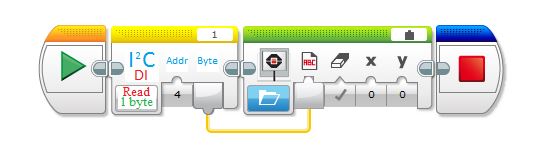
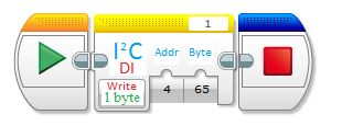
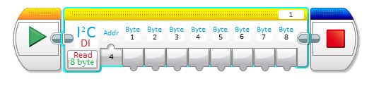
In this example, the EV3 sends some data to the Arduino. The Arduino receives it and and prints it on the Serial Monitor. If the EV3 requests for some data then the Arduino sends it a byte. You can easily modify it to send or recieve any number of bytes. There are examples for 8 byte read/write in the Github Repository.
#include <Wire.h>
#define SLAVE_ADDRESS 0x04
void setup()
{
    Serial.begin(9600); // start serial for output
    Wire.begin(SLAVE_ADDRESS);
    Wire.onReceive(receiveData);
    Wire.onRequest(sendData);
    Serial.println("Ready!");
}
int val,flag=0;
void loop()
{
  if(flag==1)
   {
     Serial.print(val);
     flag=0;
   }
}
void receiveData(int byteCount)
{
    while(Wire.available()>0)
    {
      val=Wire.read();
      flag=1;
    }
}
// callback for sending data
void sendData()
{
  Wire.write(0x45);
}
EV3 as the Master
Setting up the EV3 as the master is simple. Download the Dexter Industries EV3 blocks (Dexter.ev3b) and Import them into the Lego Mindstorms EV3 Software (Tools ->Block Import).
Learn More!
If you liked this tutorial, consider purchasing the Breadboard Adapter for LEGO Mindstorms here.