 In this HowTo, we’ll show you how to get your LEGO MINDSTORMS NXT and your Arduino to talk. In the demonstration, we use an Arduino Uno, but the example we’ve written can be used for just about any of the versions of Arduino. This example can be extended to use the Arduino as a sensor for the NXT, and to develop your own sensors for the LEGO MINDSTORMS NXT system. This is probably the fastest way to free your NXT and add your own sensors and devices: when you connect the NXT and the Arduino and the world is yours!
The NXT and the Arduino can be made to talk over I2C. In this tutorial, we setup the Arduino as an I2C slave, and the NXT as an I2C master. The NXT must always be a master and can never be a slave. Although it’s beyond this tutorial, with clever coding and polling, the Arduino can be setup to control the NXT.
 In this example, we show you how to send commands to the Arduino from the NXT and how to write a program that requests data from the Arduino. Both are very similar, but different.
A little background on I2C and the NXT. I2C is called a “two wire interface”, because it uses two wires to communicate. One wire provides a clock: this makes sure that both devices are sending information at the same speed. The clock line is usually referred to as “SCL“. The other wire is for sending data (data is sent and received by both devices at the same time), and is usually referred to as “SDA“. The master (always the NXT) always controls the communications, and always sets the communications clock for both devices. The device being controlled is referred to as the slave. When the master sends a command, the slave drops everything and listens. When the master demands information, the slave provides that information.
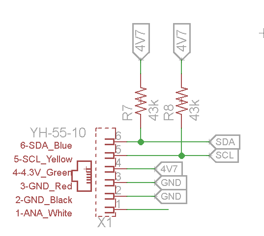
Diagram of the Pullup Resistors used to connect an I2C line to the NXT.
I2C on the NXT requires a pullup resistor. These resistors go between the SDA and 4.7 V line, and the SCL and 4.7V line.
Typically resistor values of 82k are used. If the device you are communicating with is operating at 3.3V (rather than 4.7V) you can use 43k resistors. Resistor values are important to ensuring you can communicate at a fast speed with the NXT.
If you use the Dexter Industries Breadboard Adapter for the LEGO MINDSTORMS NXT the pullup resistors are already built into the board.
Setting up the Hardware.
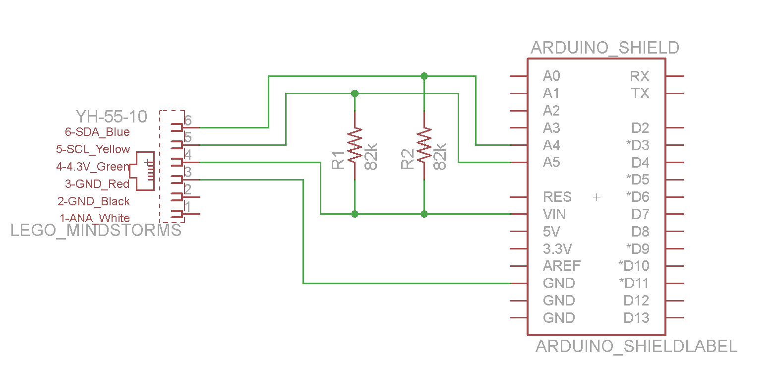
First, a schematic of what we’re aiming for. The schematic shows the NXT plug on the left hand side of the drawing, and the Arduino on the right hand side. We will need ground to be connected, and if you’re going to power your Arduino off the LEGO Mindstorms system, you will need the 4.3V connected to the VIN pin on the Arduino. Notice the pullup resistors connected from SDA and SCL to the 4.3V line. SDA on the Arduino is A4, and SCL is A5.
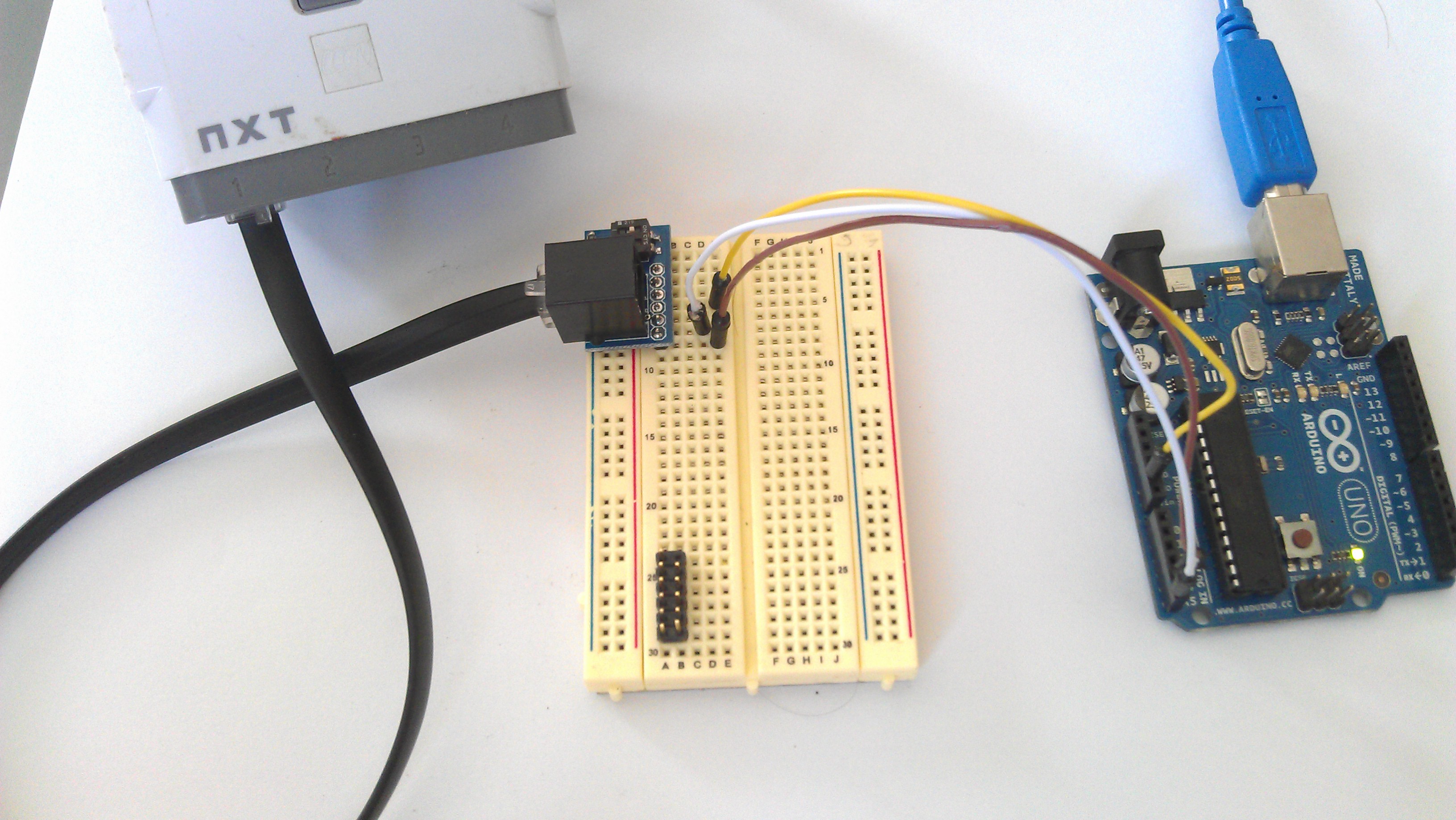
The setup we’ll wire together will look like this: NXT –> Breadboard Adapter –> Arduino. You can see an overarching view of everything below.
In this example, we’re going to connect only the SDA, SCL lines (for communications) and the ground (GND) line to equalize the communication voltages. In this example, we power the Arduino with the USB line (which we keep hooked up to our computer); however, you could easily power your Arduino with the NXT: simply connect the 4.7V line (VCC) to the “VIN” connection on the Arduino. This should provide the necessary power to power the Arduino, but be sure not to overload the NXT (recomended 50 mA current consumption as a maximum by LEGO).
Connecting to the Arduino:
The Arduino Side
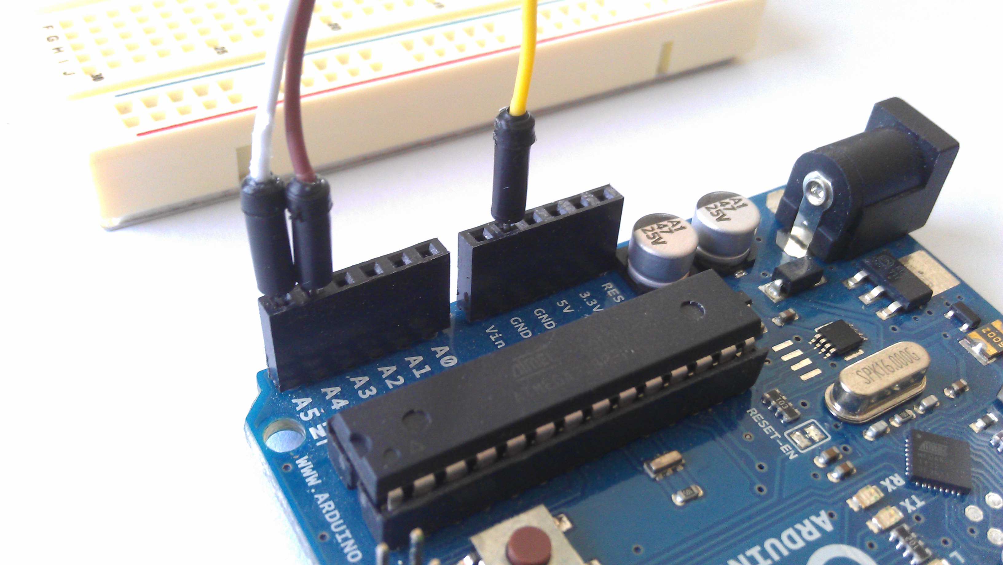
First, place on jumper into a GND port on the Arduino. Place one jumper on A5 (SCL, the clock line) of the Arduino Uno, and one jumper on A4 (SDA, the data line). In the picture on the right, you can see that we placed the Yellow jumper into GND, the Green Jumper into SDA (A4) and the White jumper into SCL (A5).
Connecting to the NXT:
 The easiest way to connect this up to the NXT is to use the Breadboard adapter (outline shown to the right). To the right you can see the pin positions of SDA and SCL, as well as GND. Again, same colors go in the same spots: SDA, the Green wire in our example, is connected to SDA on the breadboard. Ditto for SCL and GND.
Just to clarify: SDA –> SDA ; SCL –> SCL.

The LEGO MINDSTORMS side of things.
You can hack together a custom adapter pretty easily: cut off one end of the standard NXT black cord, and open up the wires. SDA and SCL are yellow and blue, while the gnd line is black. You’ll need an 82k resistor in between the SDA and VCC (green wire) and SCL and VCC.
In these pictures, the following colors correspond to these lines:
- Yellow: Ground
- White: SCL
- Brown: SDA
On the Arduino Side, we will connect the SDA, SCL, and Ground into the shield.
The Arduino Side
Software:
We’ll divide this into two parts: the Arduino software, and the NXT software. The software for the Arduino does not change: it is the same software for each programming language. We will show the NXT software in Labview for LEGO MINDSTORMS, and RobotC.
All of the code can be downloaded from this package.
Setting the Arduino up for I2C: Assigning an Address
In both of our Arduino examples, we have to setup a few things to get going. We need to select a slave address. In this example, we set the slave address to 0x0A, which is hexadecimal. In decimal, this is 10. In binary, this is 00001010. The LEGO MINDSTORMS system does something called bit shifting: you need to add a 0 at the end of the address when you call on it. So with our Arduino set to address 0x0A (binary: 00001010), we will call address 0x14 (00010100). Notice how everything shifted to the left, and we added a zero on the right? Helpful hint: Microsoft Windows 7 comes packaged with a calculator, and that calculator can be run in “Programmer” (hit “Alt-3”). On the left side you can choose to display your numbers in hex, decimal, and binary. This makes it easy to go back and forth between the three types of numbers.
Arduino As Slave Receiver:
In this example, the Arduino will receive data from the master. The NXT simply says “here’s some data” and the Arduino says “thanks for the data”. This is a very simple setup and most sensors operate as a Slave Receiver and Sender. This example can be really useful if you’re setting your Arduino up as a motor controller or for LED output.
In this example, we’ve initiated the Serial line on the Arduino. The NXT sends a command to the Arduino, and the Arduino sends that data to the computer. You could rewrite it though so that the data being sent is the power of an LED, or the speed of a motor.
[sourcecode 1=”language=”cpp”” language=”gutter=”] // I2C Slave Receiver// How to send data from the LEGO Mindstorms NXT to the Arduino.
// For LEGO Mindstorms
// Demonstrates how to connect a LEGO MINDSTORMS to an Arduino and Send commands.
// A4 – SDA
// A5 – SCL
// See our website, www.dexterindustries.com/howto for more information on the physical setup.
#include
void setup()
{
Wire.begin(0x0A); // Start I2C on Address 0x0A
Wire.onReceive(receiveI2C); // Receive Event from Master
Serial.begin(9600); // We will spit it back out on the serial line.
}
void loop()
{
delay(1);
}
// When data is received, this function is called.
void receiveI2C(int bytesIn)
{
while(1 < Wire.available()) // loop through all but the last
{
char c = Wire.read(); // Receive the incoming byte
Serial.print(c); // Print the incoming byte as a character on the Serial line.
}
int x = Wire.read(); // Read the incoming byte
Serial.println(x); // Print the incoming byte
}
[/sourcecode]
Arduino Slave Receiver and Sender:
In most work you do with the Arduino, you’ll want send data to the Arduino, and have it reply back. The NXT sends a register number it wants data from, and the Arduino responds back with the information. Most sensors work this way: you can get the sensor information (name, type, etc) on one register, the data it is sensing (temperature, pressure, etc) and maybe even rewrite settings via registers.
The setup is again pretty simple. In this example, we have started Wire’s “onRequest” function. Based on the information that is requested (the register sent over) data is sent back to the NXT. In this example, we’ve setup a simple case: if the NXT requests 0x01, we send back the text “Dexter” and if it requests anything else, the Arduino sends back “Industries”.
[sourcecode 1=”language=”cpp”” language=”gutter=”] // I2C Slave Send / Receive// How to send data from the LEGO Mindstorms NXT to the Arduino.
// For LEGO Mindstorms
// Demonstrates how to connect a LEGO MINDSTORMS to an Arduino and Send commands, receive data.
// A4 – SDA
// A5 – SCL
// See our website, www.dexterindustries.com/howto for more information on the physical setup.
#include
byte read_register = 0x00;
void setup()
{
Wire.begin(0x0A); // join i2c bus with address #2
Wire.onRequest(requestEvent); // Sending information back to the NXT!
Wire.onReceive(receiveI2C); // Receiving information!
}
void loop()
{
delay(100);
}
// When data is received from NXT, this function is called.
void receiveI2C(int bytesIn)
{
read_register = bytesIn;
while(1 < Wire.available()) // loop through all but the last
{
read_register = Wire.read(); // The incoming byte tells use the register we will use.
Serial.print(read_register); // Print the incoming byte as a character on the Serial line.
}
int x = Wire.read(); // Read the incoming byte
Serial.println(x); // Print the incoming byte
}
// Based on the read_register value we will return either Dexter or Indusries.
// This can be expanded to have 256 different registers that can be updated and accesed
// when the master calls for them.
void requestEvent()
{
// We’re going to send a fixed response. However,
// you can use a switch case here and send different responses
// based on a register system.
if(read_register == 0x01){
Wire.write(“Dexter “); // respond with message of 10 bytes
}
else{
Wire.write(“Industries”); // respond with message of 10 bytes
} // as expected by master
}
[/sourcecode]
NXT: RobotC
Let’s shift back to the NXT. If you wanted to talk over I2C with your Arduino from RobotC, Xander has done a much better job of explaining in-depth how to do that. We recommend looking at his blog. Below is some code, but we’d like to point out some critical things going on:
- We setup an array called I2Cmessage[]. This is the array of data we send over to the Arduino.
- We read the Arduino’s response back into an array called “I2Creply”.
- In the second example, we print out the results of that array to the debug stream on RobotC.
- You can see that the Arduino Address is set to 0x14, and the Port is set to S1.
RobotC: Slave Send
[cpp language=”true”] #pragma config(Sensor, S1,TIR,sensorI2CCustom)/*
*/
// First, define the Arduino Address
// Address is 0x0A on the Arduino: (Binary) 1010
// Bit shifted out with one 0, that becomes: (Binary) 10100
// Which is 0x14
#define ARDUINO_ADDRESS 0x14
#define ARDUINO_PORT S1
ubyte I2Cmessage[22];
ubyte I2Creply[20];
void i2c_read_registers_text(ubyte register_2_read, int message_size, int return_size){
memset(I2Creply, 0, sizeof(I2Creply));
I2Cmessage[0] = message_size; // Messsage Size
I2Cmessage[1] = ARDUINO_ADDRESS;
I2Cmessage[2] = register_2_read; // Register
sendI2CMsg(S1, &I2Cmessage[0], return_size);
wait1Msec(20);
readI2CReply(ARDUINO_PORT, &I2Creply[0], return_size);
string returned_string;
ubyte *I2Creply_pointer[20];
memcpy(I2Creply_pointer, I2Creply, sizeof(I2Creply));
StringFromChars(returned_string, I2Creply_pointer);
writeDebugStreamLine(returned_string);
writeDebugStreamLine(” “);
}
void i2c_write_registers(ubyte register_2_write, int message_size, int return_size, ubyte byte1, ubyte byte2, ubyte byte3, ubyte byte4){
memset(I2Creply, 0, sizeof(I2Creply));
message_size = message_size+3;
I2Cmessage[0] = message_size; // Messsage Size
I2Cmessage[1] = ARDUINO_ADDRESS;
I2Cmessage[2] = register_2_write; // Register
I2Cmessage[3] = byte1;
I2Cmessage[4] = byte2;
I2Cmessage[5] = byte3;
I2Cmessage[6] = byte4;
sendI2CMsg(ARDUINO_PORT, &I2Cmessage[0], return_size);
wait1Msec(20);
}
/*
*/
task main()
{
while(true){
i2c_write_registers(0x01, 0x01, 0x00, 0x0A, 0, 0, 0);
writeDebugStreamLine(“Written!”);
wait1Msec(1000);
}
}
[/cpp]RobotC: Slave Send and Receive
[cpp language=”true”] #pragma config(Sensor, S1,TIR,sensorI2CCustom)/*
How to connect your LEGO MINDSTORMS NXT with an Arduino.
http://www.dexterindustries.com/howto/
*/
// First, define the Arduino Address
// Address is 0x0A on the Arduino: (Binary) 1010
// Bit shifted out with one 0, that becomes: (Binary) 10100
// Which is 0x14
#define ARDUINO_ADDRESS 0x14
#define ARDUINO_PORT S1
ubyte I2Cmessage[22];
char I2Creply[20];
void i2c_read_registers_text(ubyte register_2_read, int message_size, int return_size){
memset(I2Creply, 0, sizeof(I2Creply));
message_size = message_size+3;
I2Cmessage[0] = message_size; // Messsage Size
I2Cmessage[1] = ARDUINO_ADDRESS;
I2Cmessage[2] = register_2_read; // Register
sendI2CMsg(S1, &I2Cmessage[0], return_size);
wait1Msec(20);
readI2CReply(ARDUINO_PORT, &I2Creply[0], return_size);
int i = 0;
while(true){
writeDebugStream(“%c”, I2Creply[i]);
i++;
if(I2Creply[i] == 0) break;
}
writeDebugStreamLine(” “);
}
task main()
{
while(true){
// i2c_write_registers(0x01, 0x01, 0x00, 0x0A, 0, 0, 0);
i2c_read_registers_text(0x01, 0, 10); // Here we’re going to get back “Dexter” because we’re writing to the 0x01 register.
i2c_read_registers_text(0x00, 0, 10); // Here we’re going to get back “Industries” because we’re weriting to the 0x00 register.
wait1Msec(1000);
}
}
[/cpp]Labview for LEGO MINDSTORMS
Reading I2C from LVLM is easy. You need to do a few things to get it working.
- Setup the sensor port. You only need to do this once. When doing this, if starting from scratch, take advantage of LVLM’s built in defaults: right click on the port and select “Create –> Constant”.
- You’re going to assemble an array of bytes and feed that into the I2C Communication module.
- The address representation here is 0x14. Be careful: if that constant is represented in decimal format, be sure to convert the number over to decimal (20).
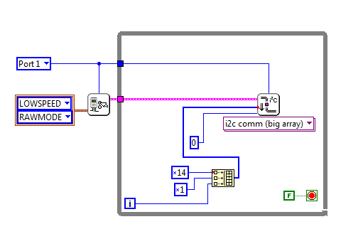
Here’s what the simple “Slave Sender” code looks like. Click for a larger view.
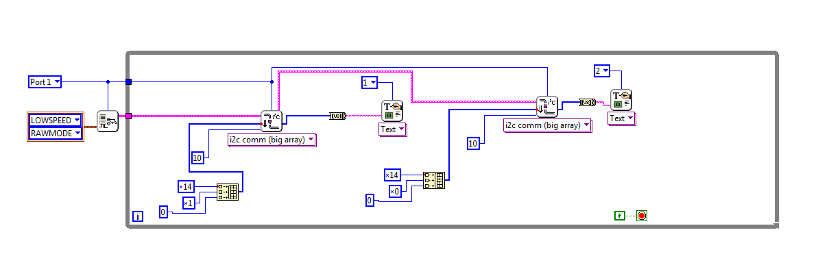
In the more advanced code, where we send and receive data to and from the Arduino, our code is a little more complex. Before we begin, some important things to note:
Again, we’re initiating the sensor.
The first thing we do is send the data requested. However, notice we’ve attached a “10” to the I2C module. This means “we’re expecting 10 bytes back”.
The data returned is an array of bytes that contains the sentence “Dexter ” or “Industries”. We convert that to a string with the Byte Array to String Function.
That’s about it! Hope this was helpful; if there’s anything missing or you need something clarified, just mention it in the comments!
EDIT:
Matt Richardson has a really extensive library put together for connecting the LEGO Mindstorms and the Arduino on his blog here:
http://mattallen37.wordpress.com/arduino-libraries/
He has worked out some extensive functions for NXC that make it really easy to go back and forth. If you’re interested in making a more extensive project with the Arduion and LEGO, see his website!
Learn More!
If you liked this tutorial, consider purchasing the Breadboard Adapter for LEGO Mindstorms here.