 Here we will show you how to assemble the GoPiGo Servo Kit and attach it to your GoPiGo3. The servo kit can be used to attach a Raspberry Pi Camera, a Dexter Industries Distance Sensor, or an Ultrasonic Sensor. The servo kit allows your GoPiGo3 to swivel the sensor to detect objects and navigate around them.
What You’ll Need
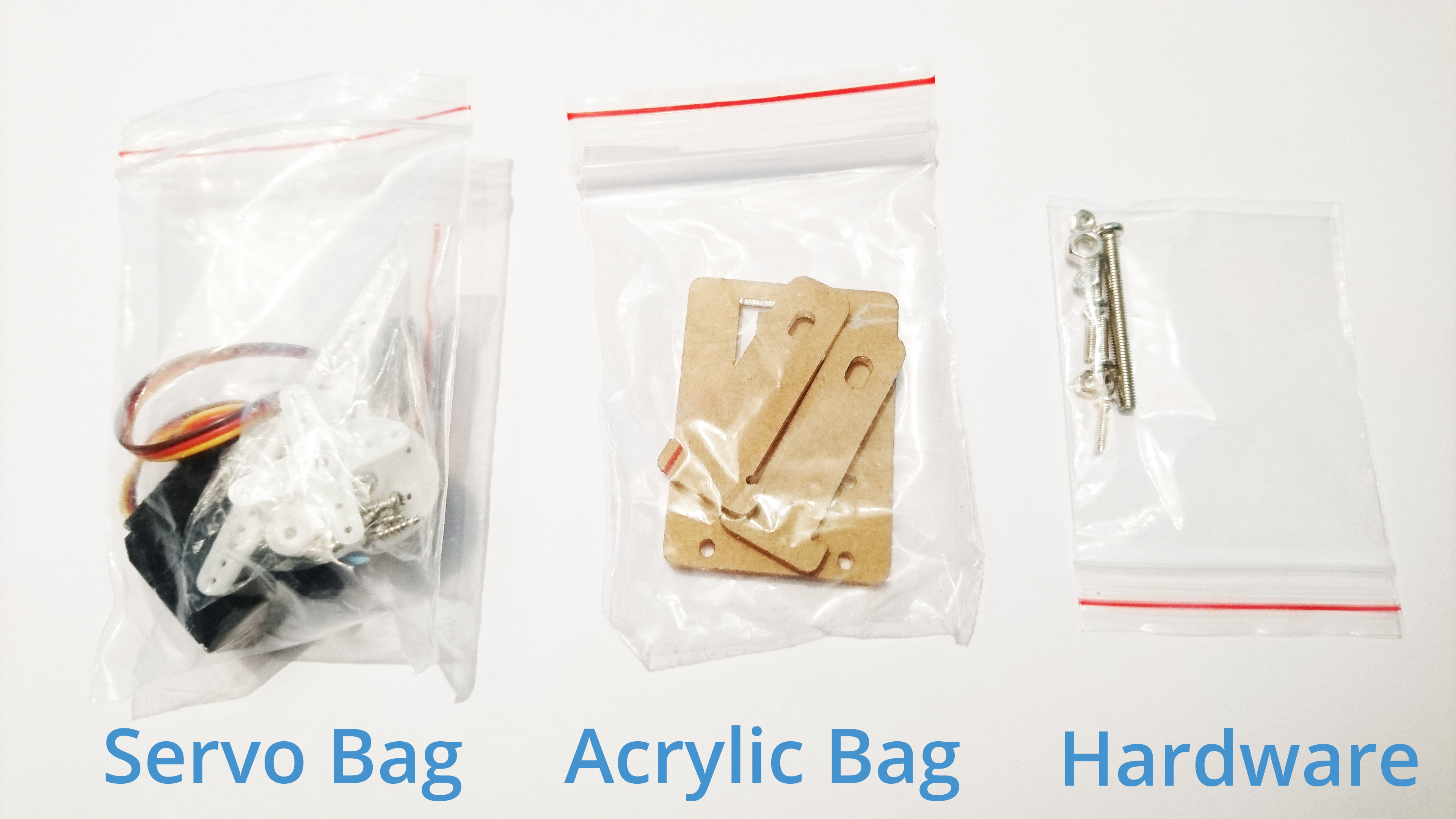
The GoPiGo Servo Kit contains the following:
- 1 bags of screws
- 1 bag of acrylic parts (labeled below as “Acrylic Bag”)
- 1 servo motor and white attachments
Assemble the Servo Kit
1. The acrylic parts will come with scratch-protective paper or plastic. Peel it off before continuing.
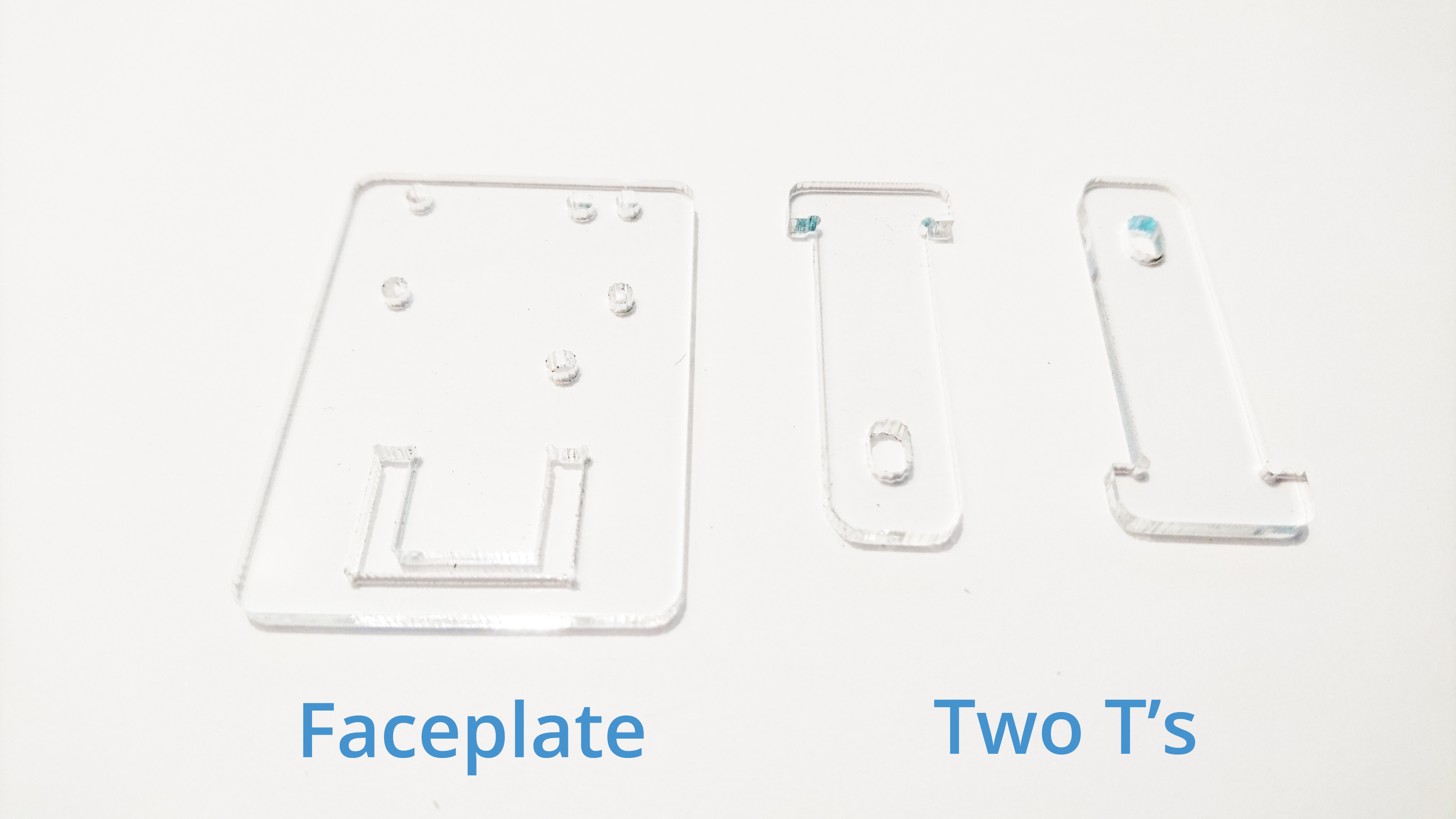
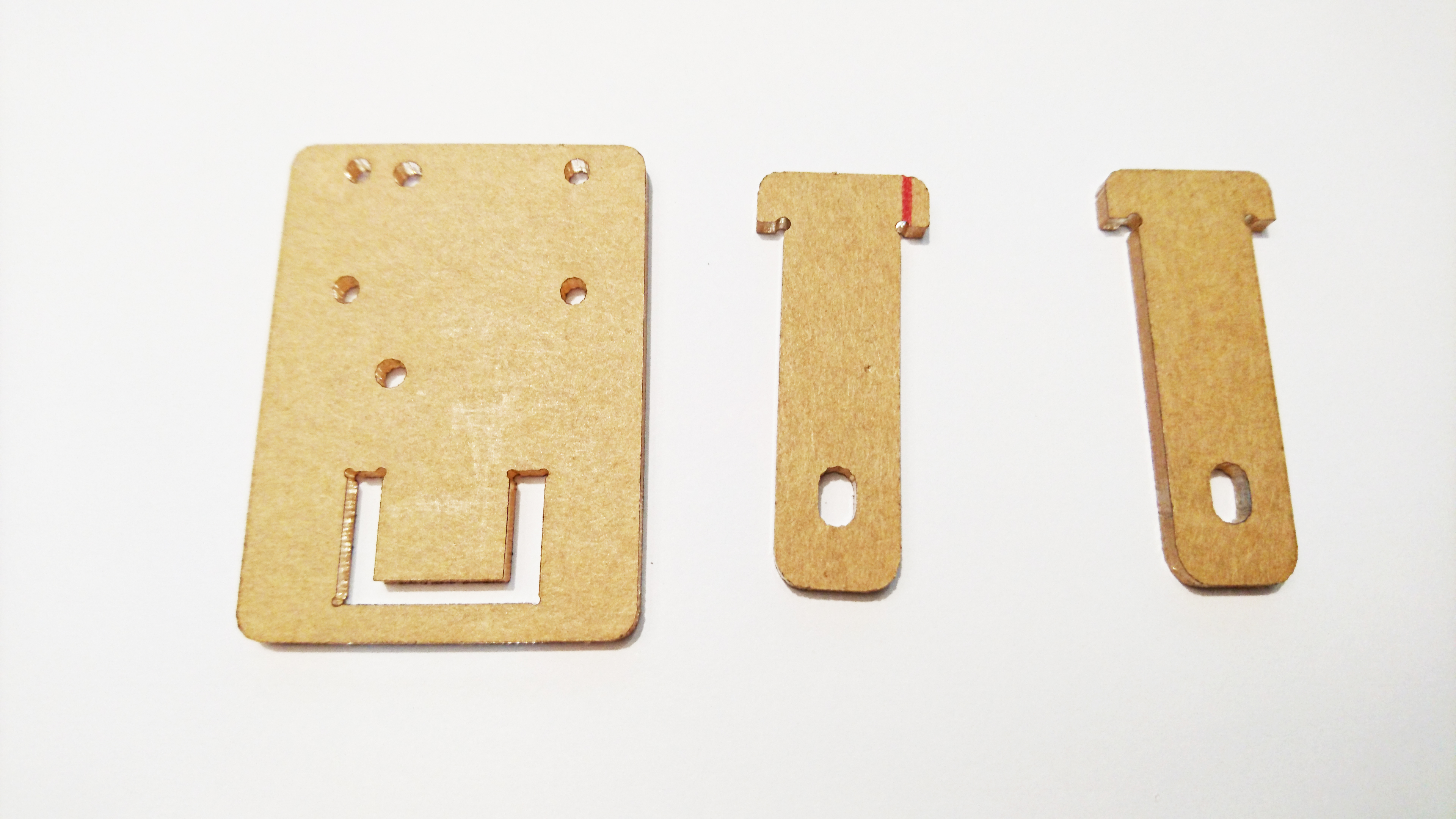
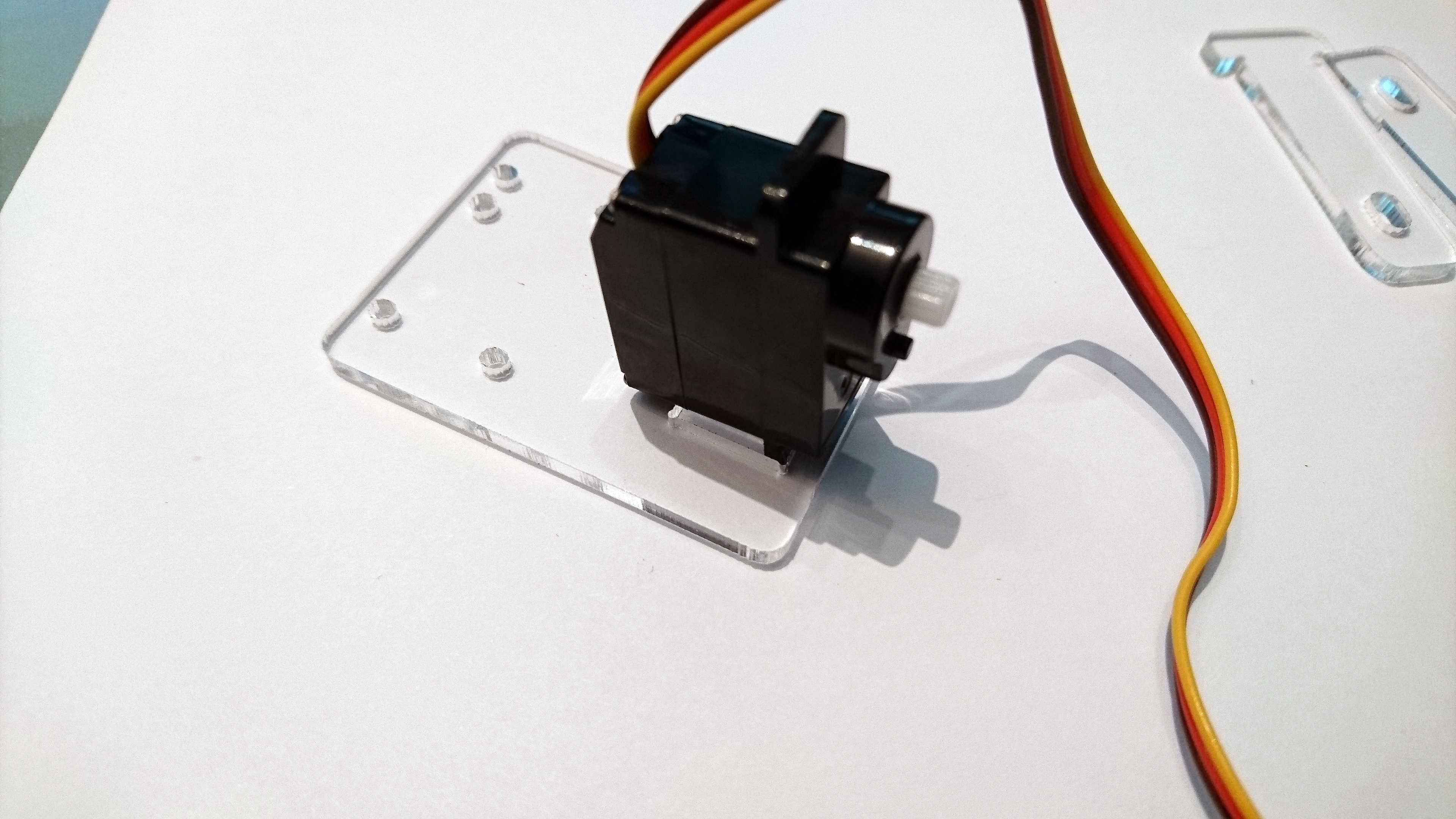
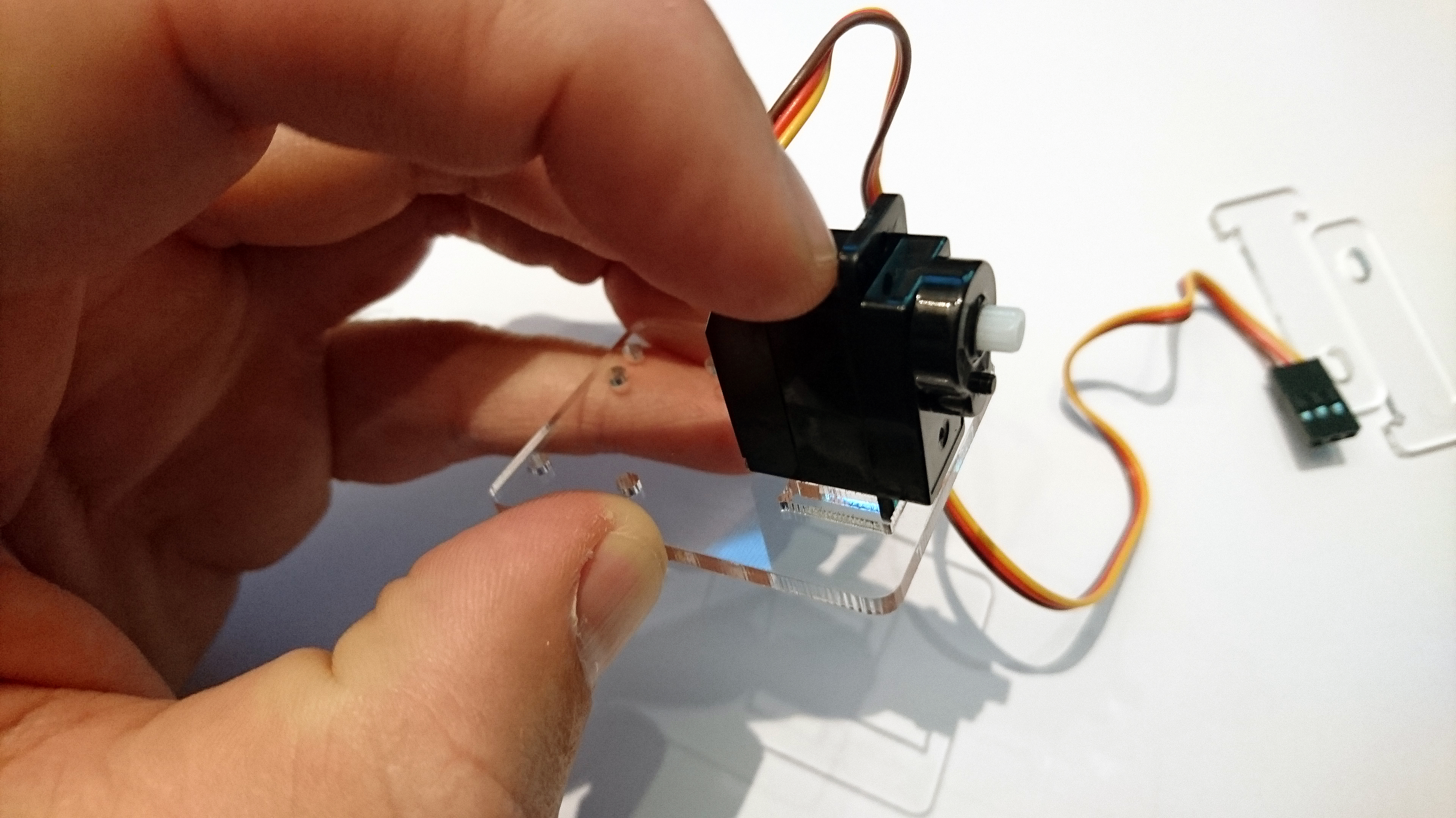
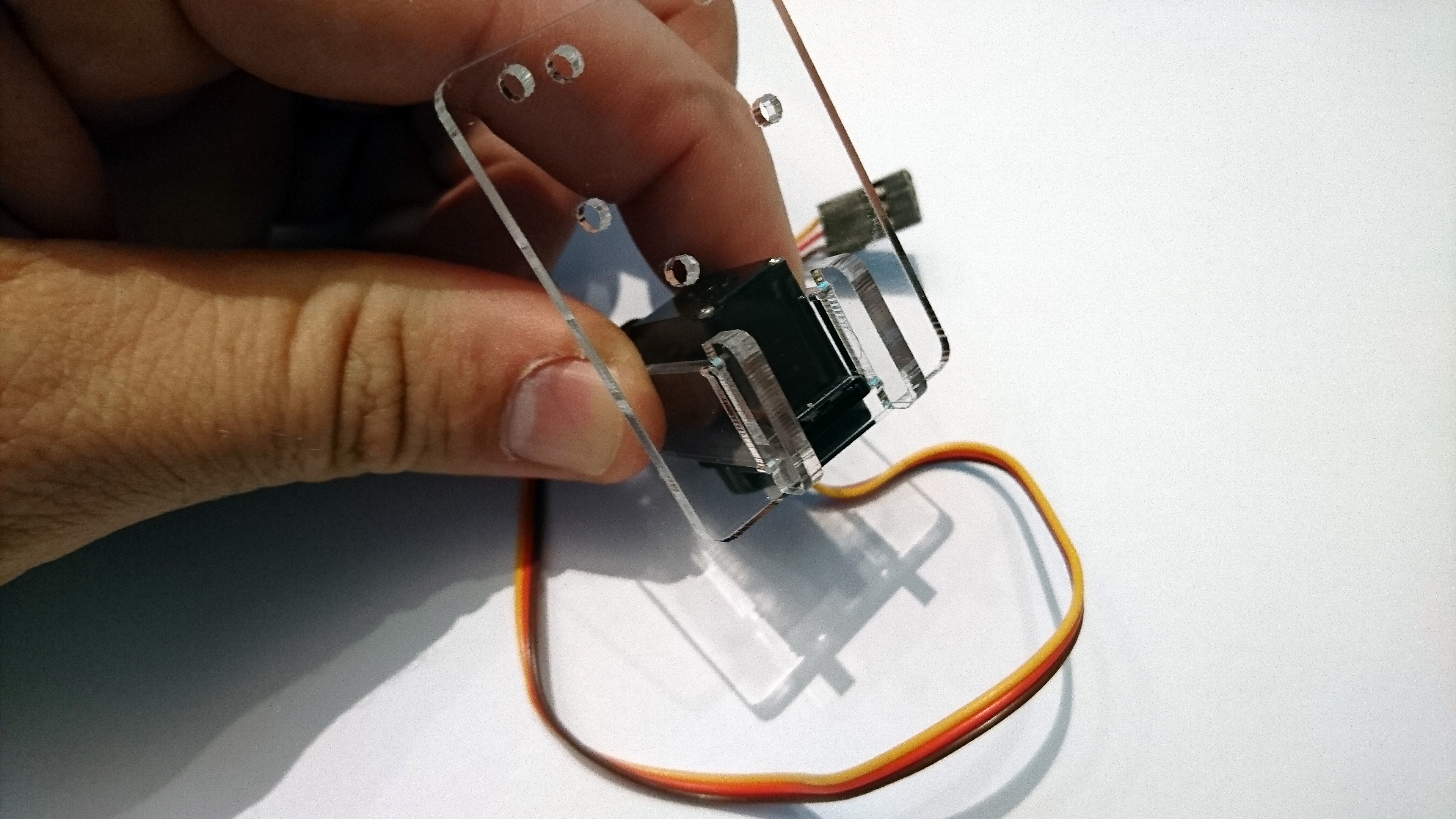
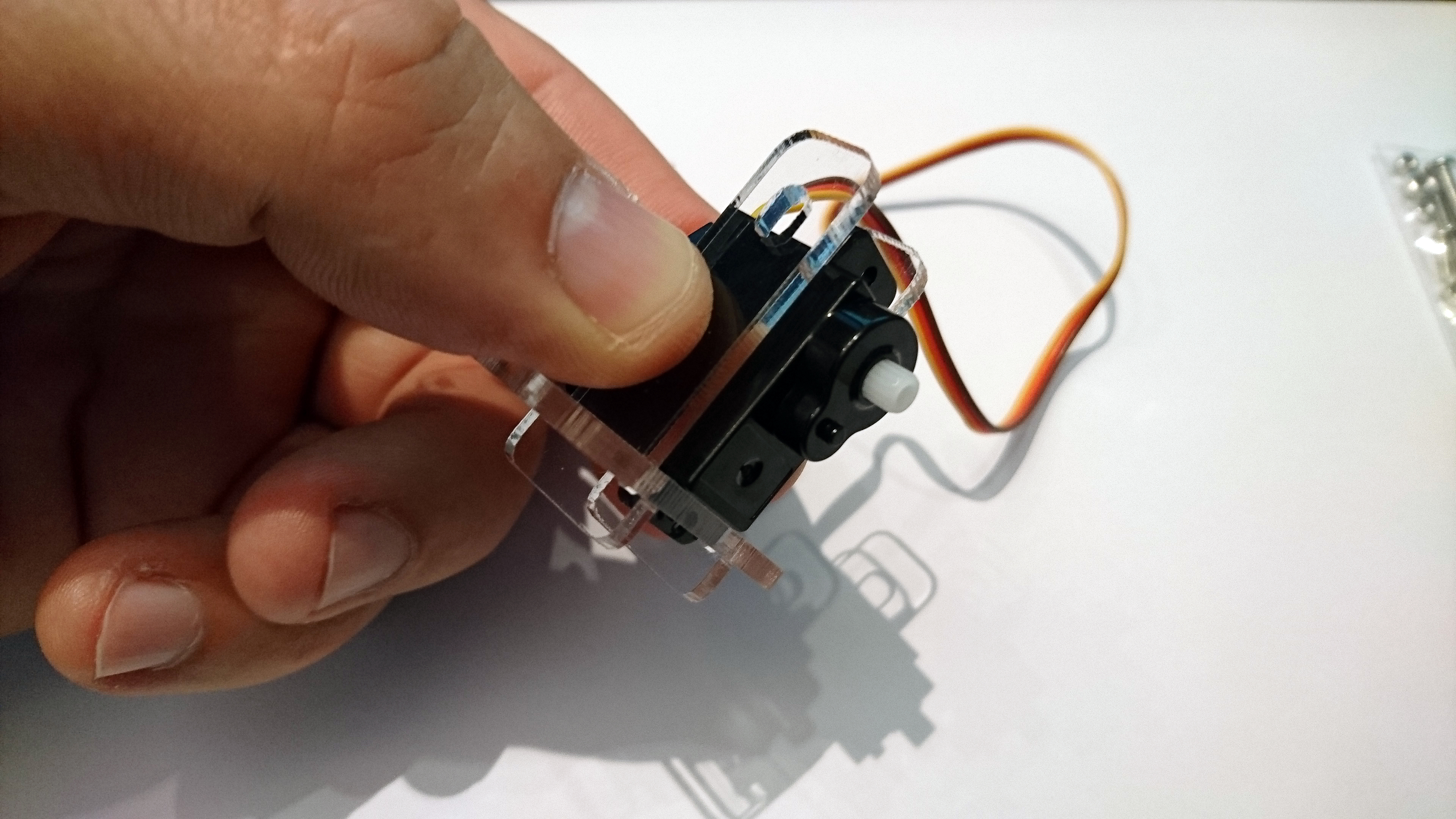
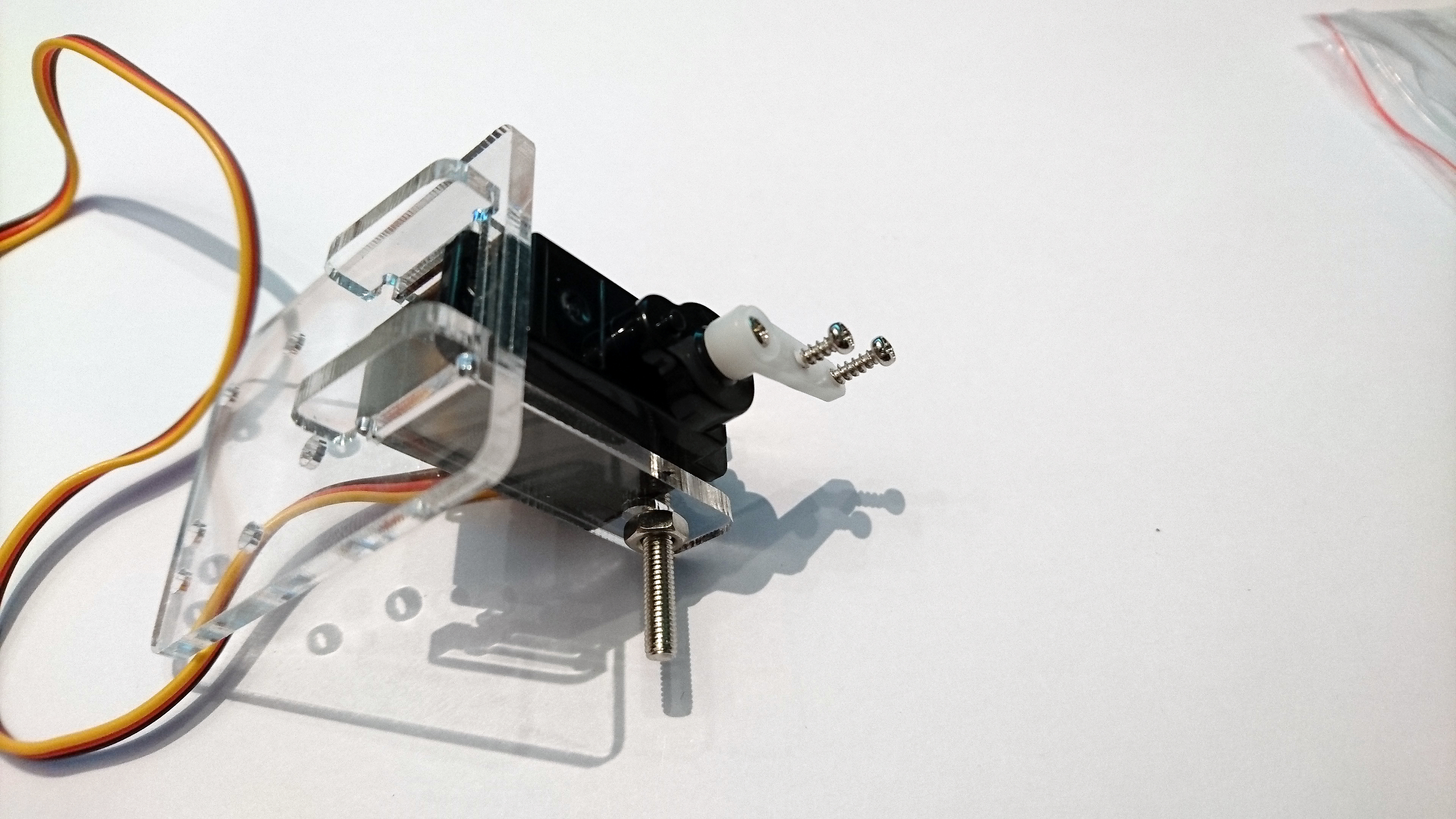
2. Next, place the servo motor into the faceplate. Three pictures are shown below of the servo placed into the faceplate. The ledge of the servo, opposite the servo shaft (the white piece of plastic coming out of the servo), should be placed through the slot on the bottom of the acrylic faceplate.
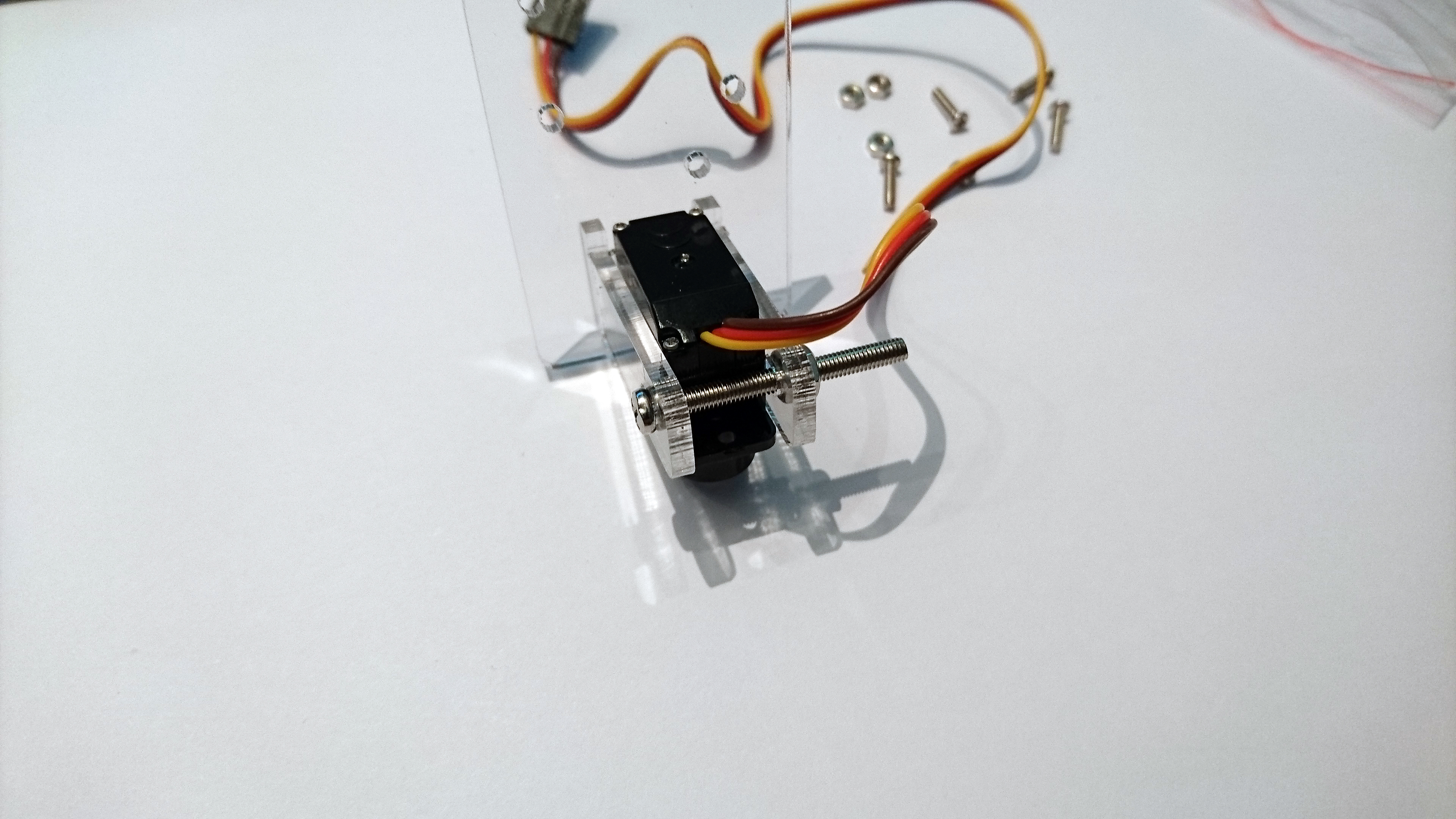
3. Slide the two “T”‘s through the front of the faceplate, alongside the servo motor. These serve as a bracket to hold the servo motor in place.
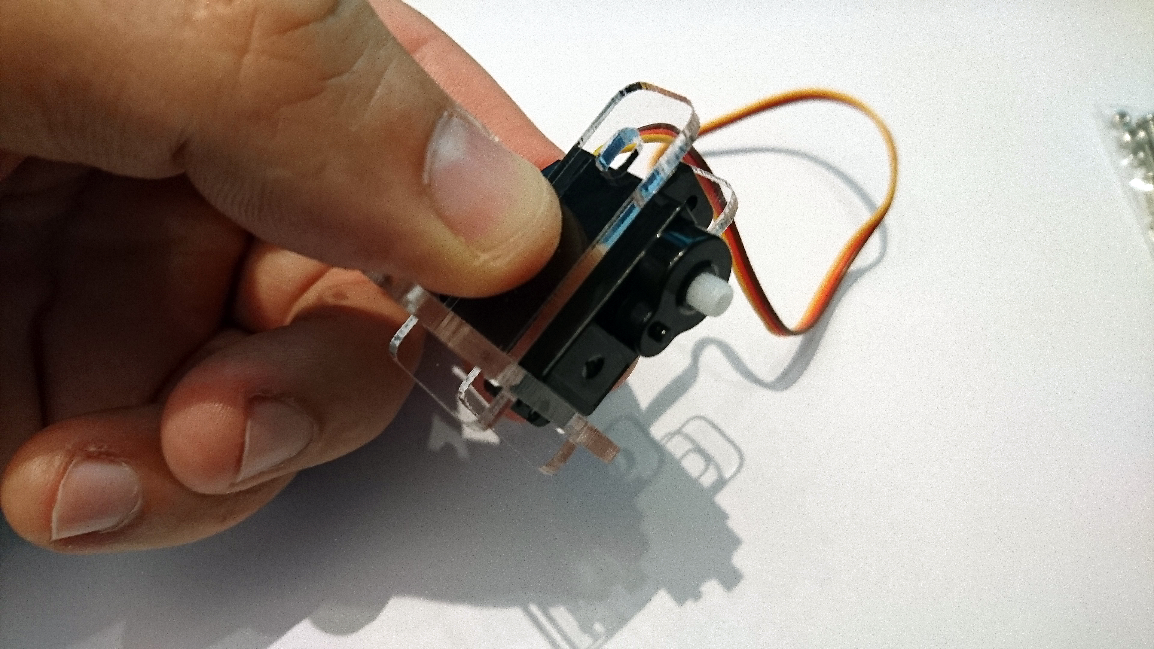
4. Insert the long screw through the two holes at the end of the “T”s.
5. In the bag with the servo, you’ll see white attachment pieces. Select the servo “Lip” from the parts, and place it on the servo shaft.
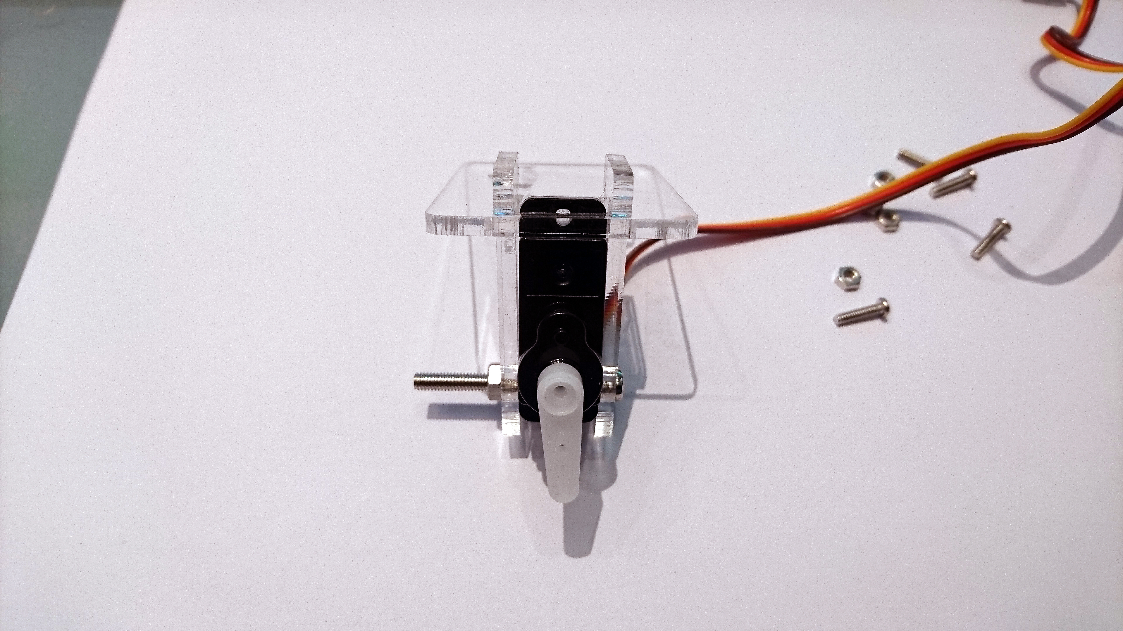
Insert one of the small wood screws through the lip and into the servo. Screw the lip in place.
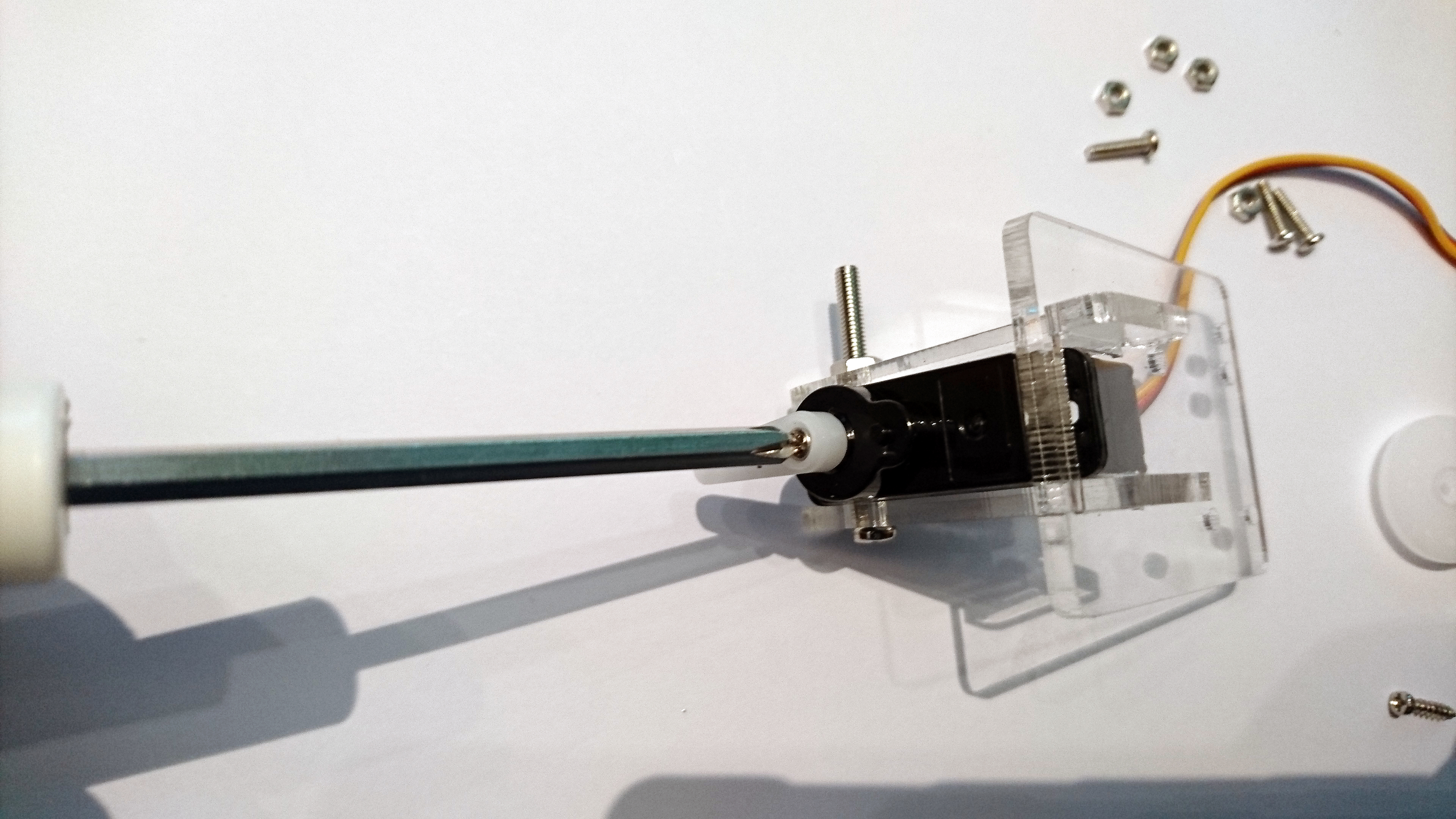
6. Insert two large wood screws into the first and third hole of the lip. Screw them in halfway to expand out the holes in the servo lip then take them out.
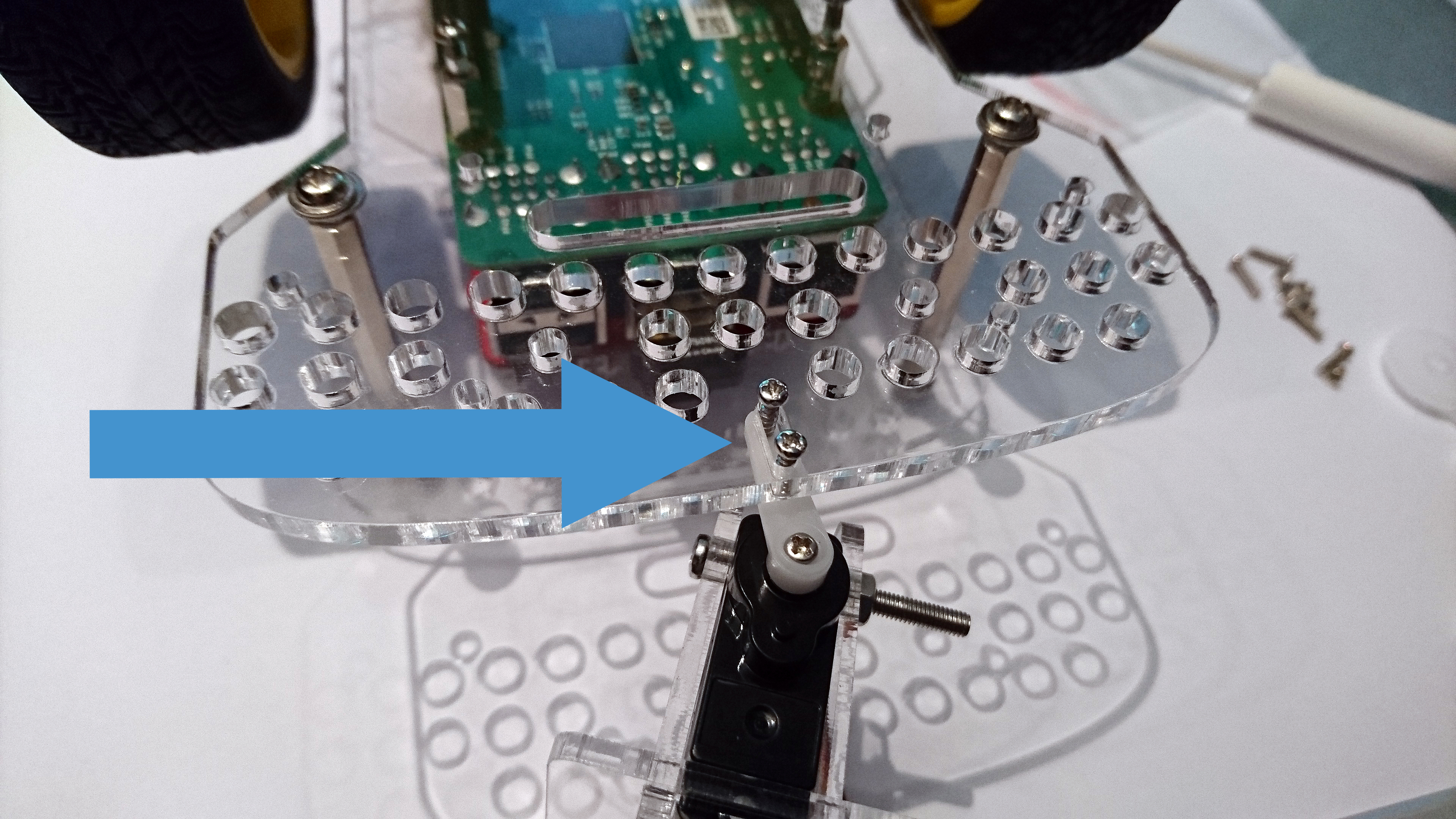
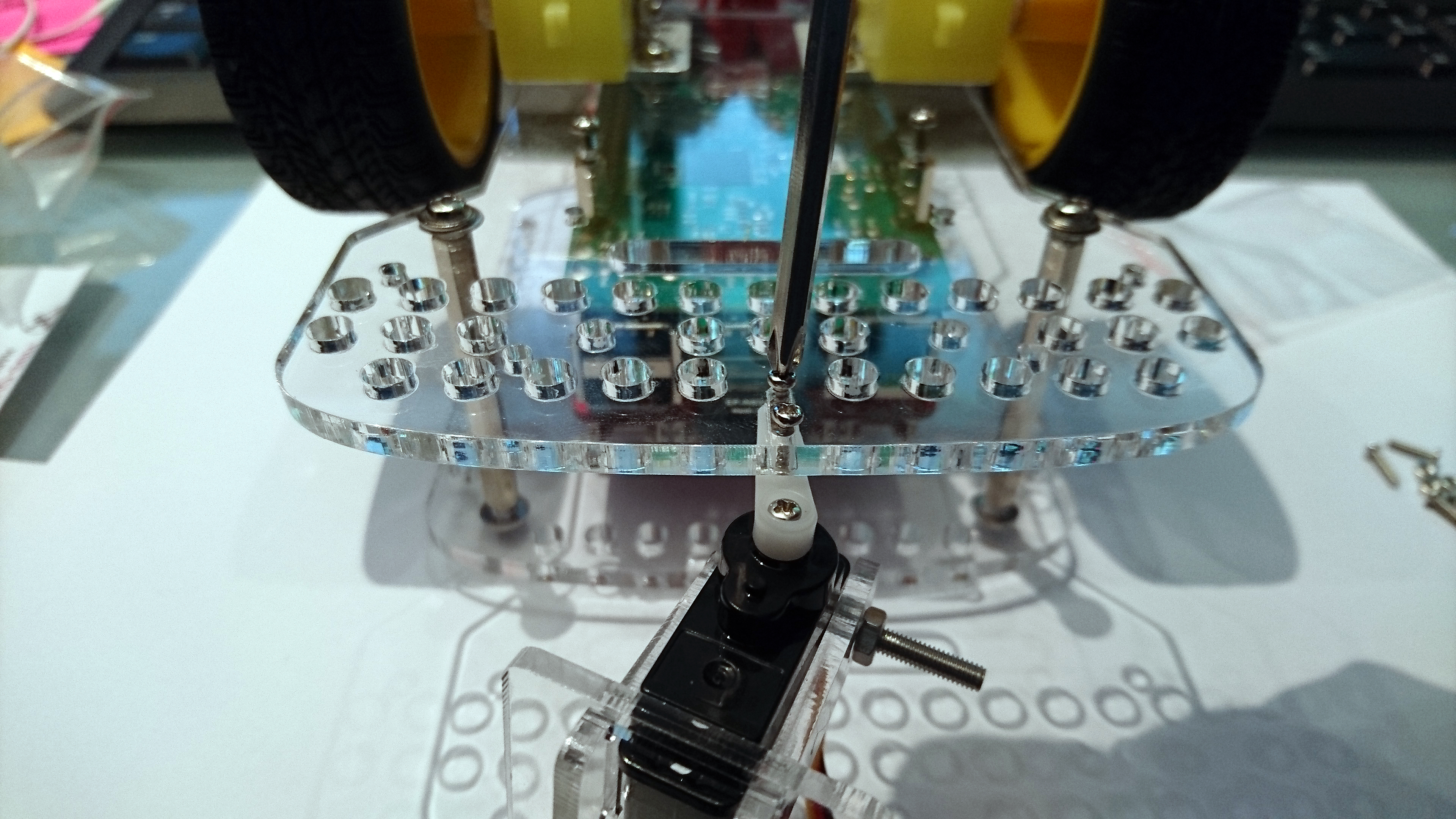
7. Attach the servo to the GoPiGo acrylic body. There is one single oval-shaped hole at the front of the GoPiGo3. Turn the GoPiGo3 upside down on a table or flat surface. The two screws should be pointing down, through the GoPiGo3 chassis, and into the servo lip.
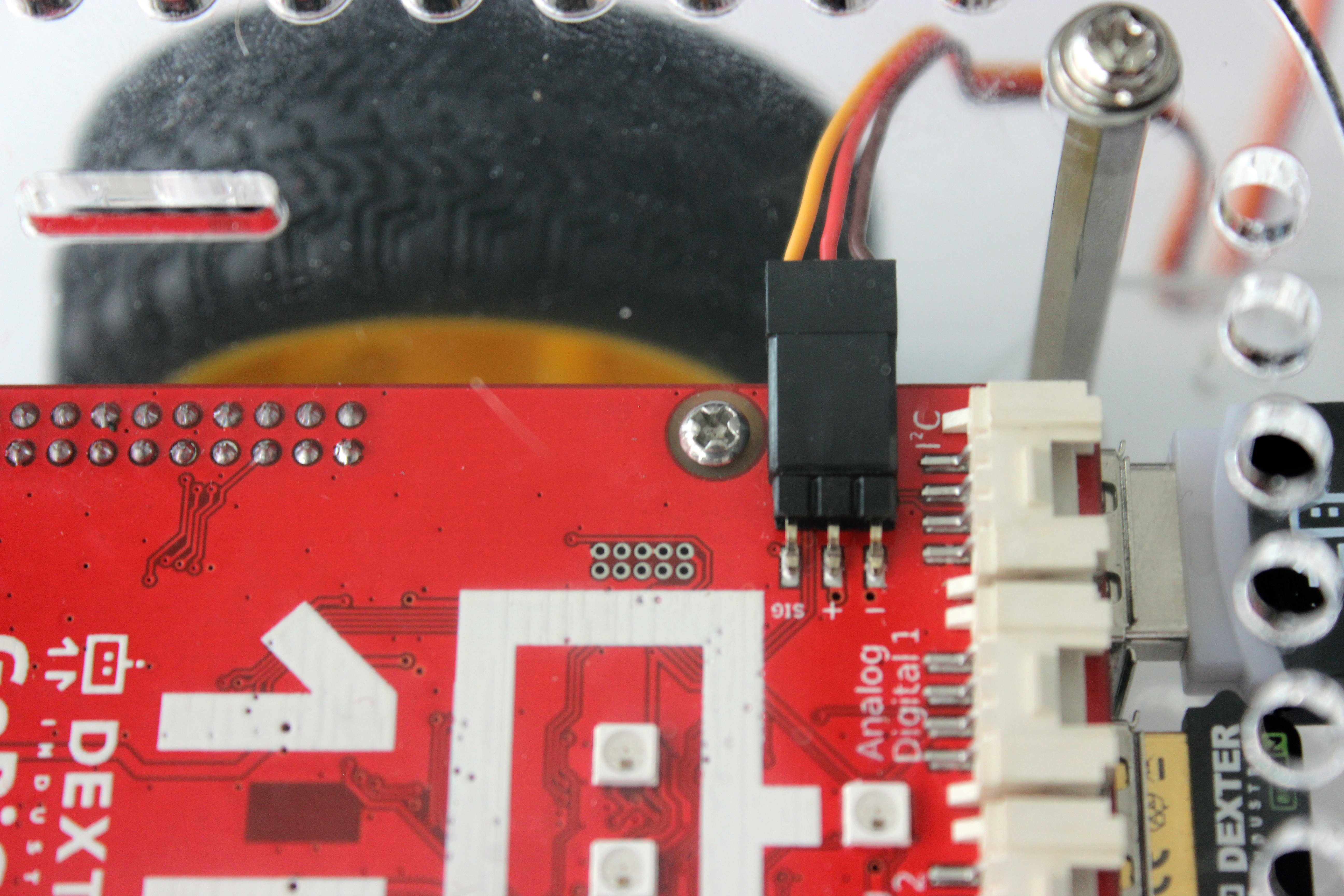
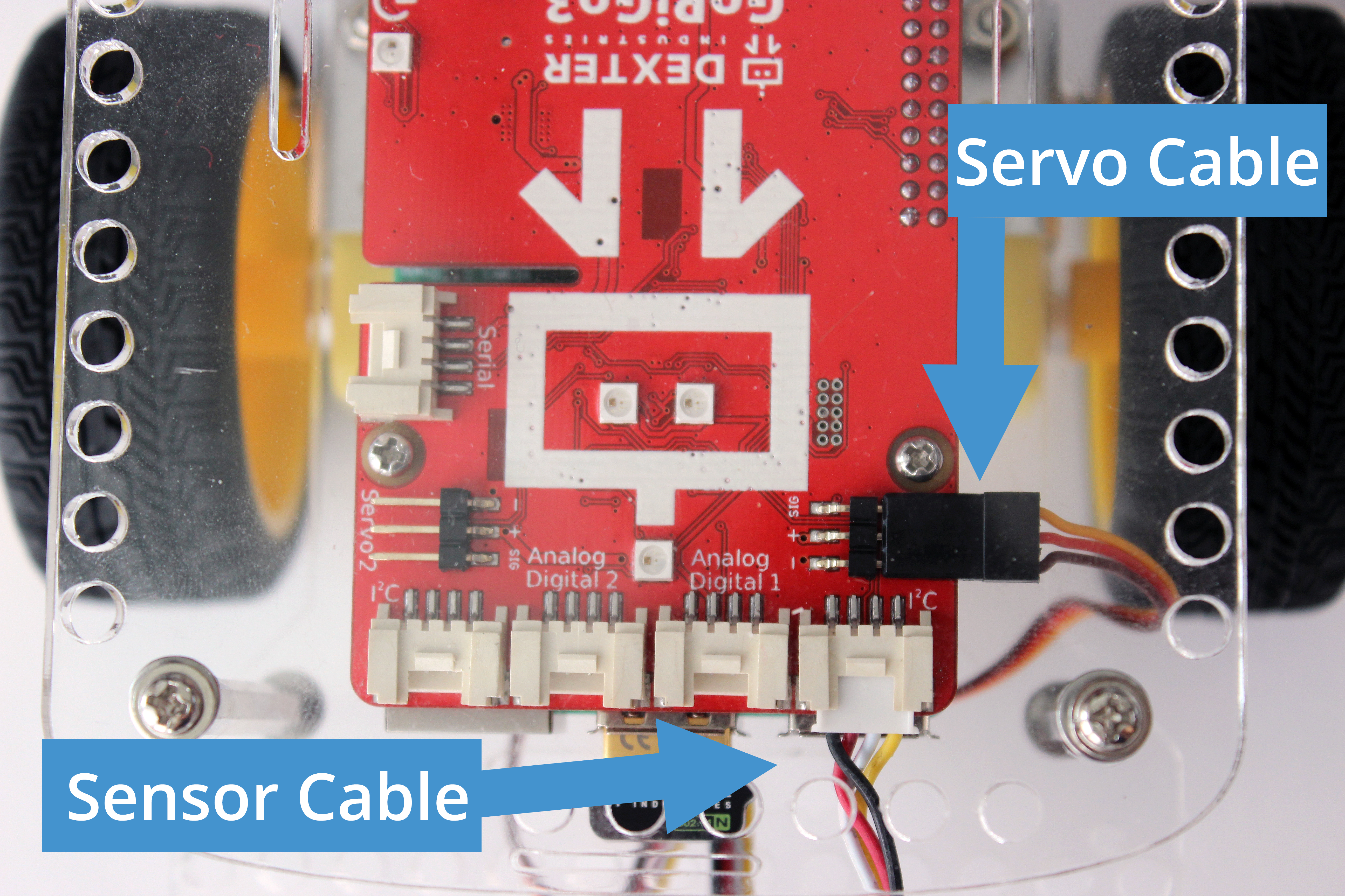
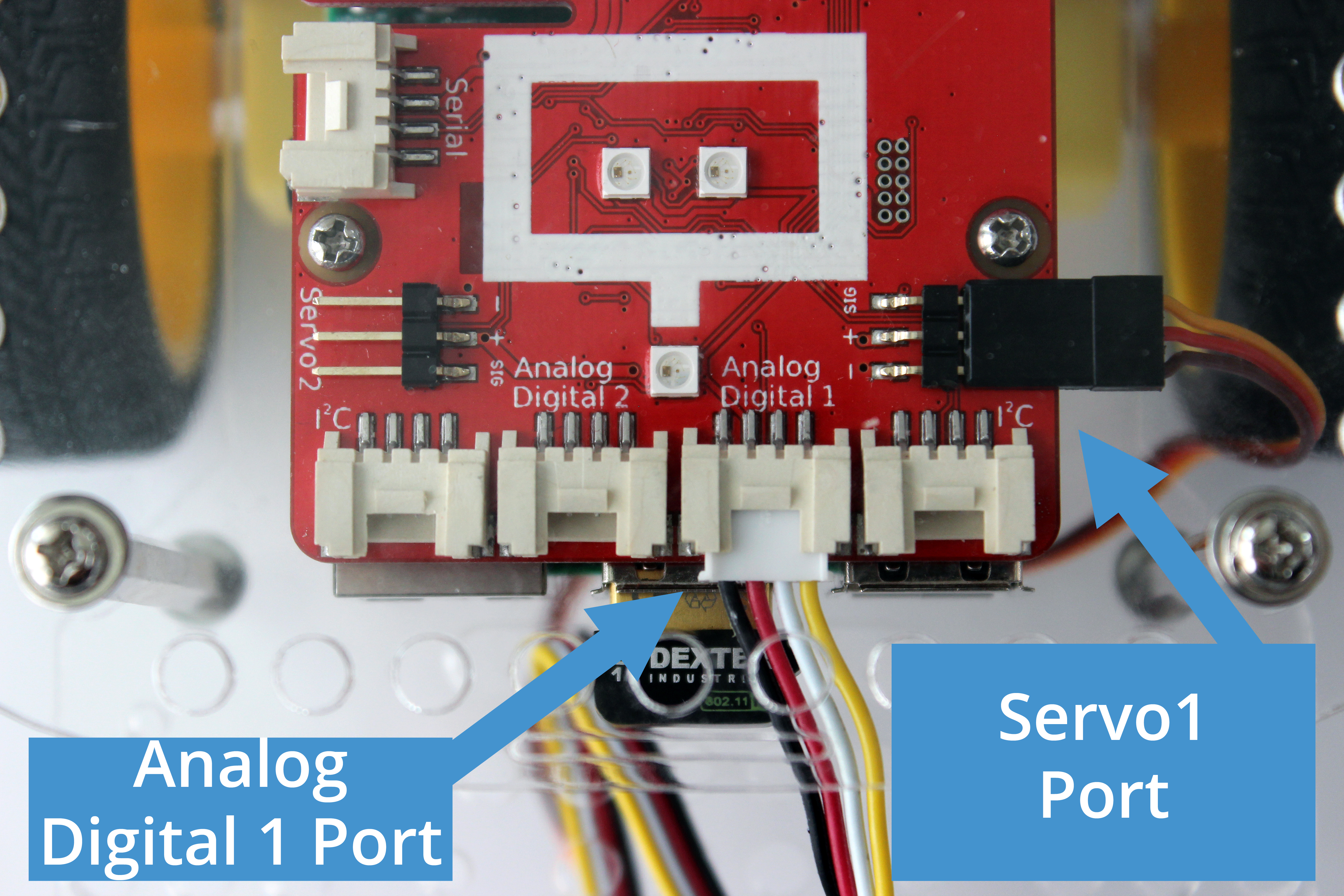
8. Connect the servo cable to the red GoPiGo3 board, on the “Servo 1” connection. These are the three-pronged pins on either side of the GoPiGo3, towards the front. Note the orientation of the servo cable in the picture: it is important that the orange wire faces the back of the GoPiGo3, and the brown wire faces the front of the GoPiGo3.
9. The servo is now properly connected to the GoPiGo3! You should be able to run a test program for the servo and see it move!
Hint: if you don’t see the servo move, check the orientation of your servo cable.
Attach the Distance Sensor
The Distance Sensor can be attached to the GoPiGo Servo.
You will need:
- Assembled GoPiGo Servo Kit
- Distance Sensor & cable
- Hardware from Servo Kit: 2 small machine screws, 2 nuts
Attach the Distance Sensor to the Servo Kit:
1. Slide two screws through the distance sensor board.
2. Then slide the screws through the two small holes at the top of the acrylic servo bracket.
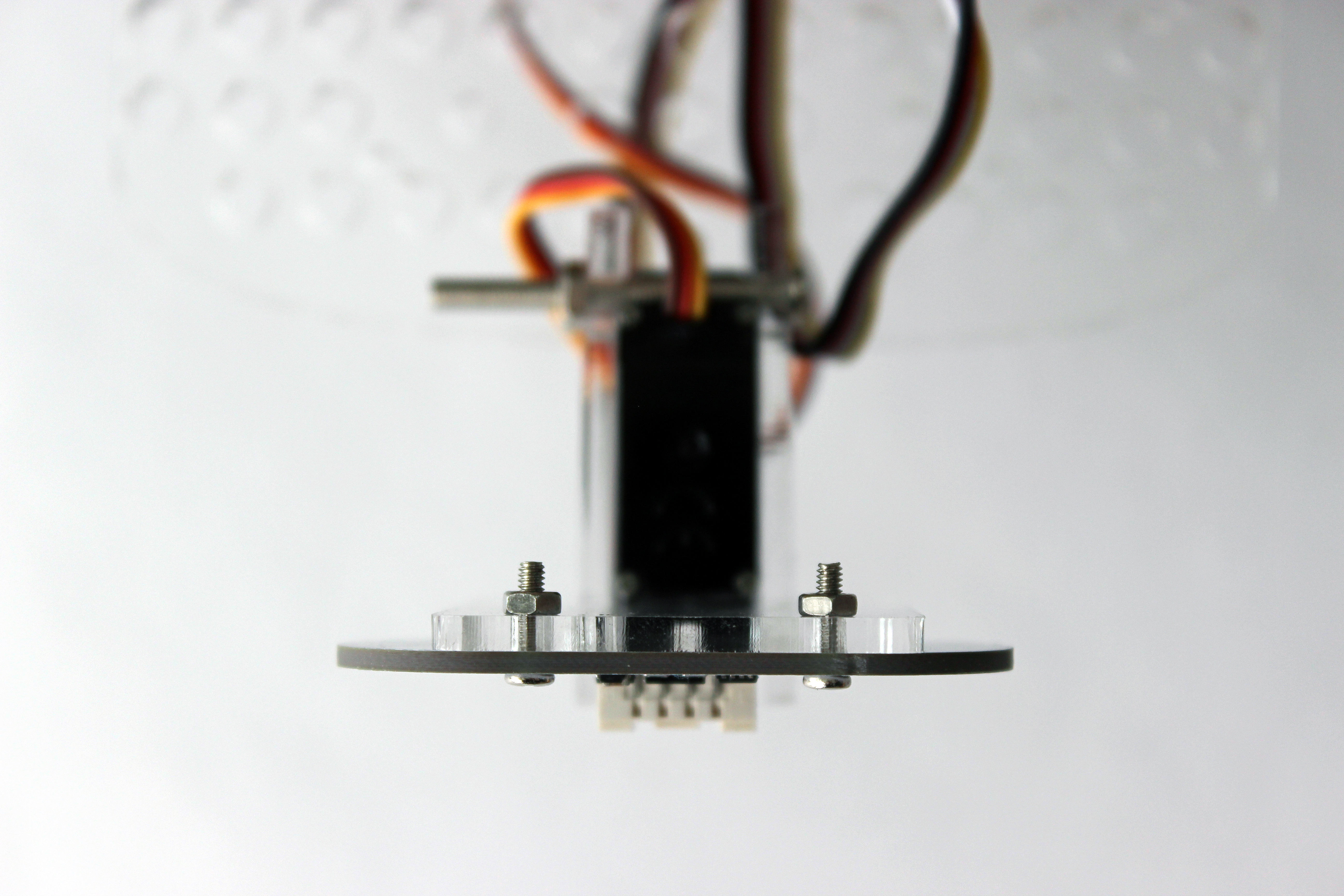
3. Attach the screws using the 2 small nuts.
4. Connect the distance sensor cable to the either of the I2C ports on the red GoPiGo3 board.
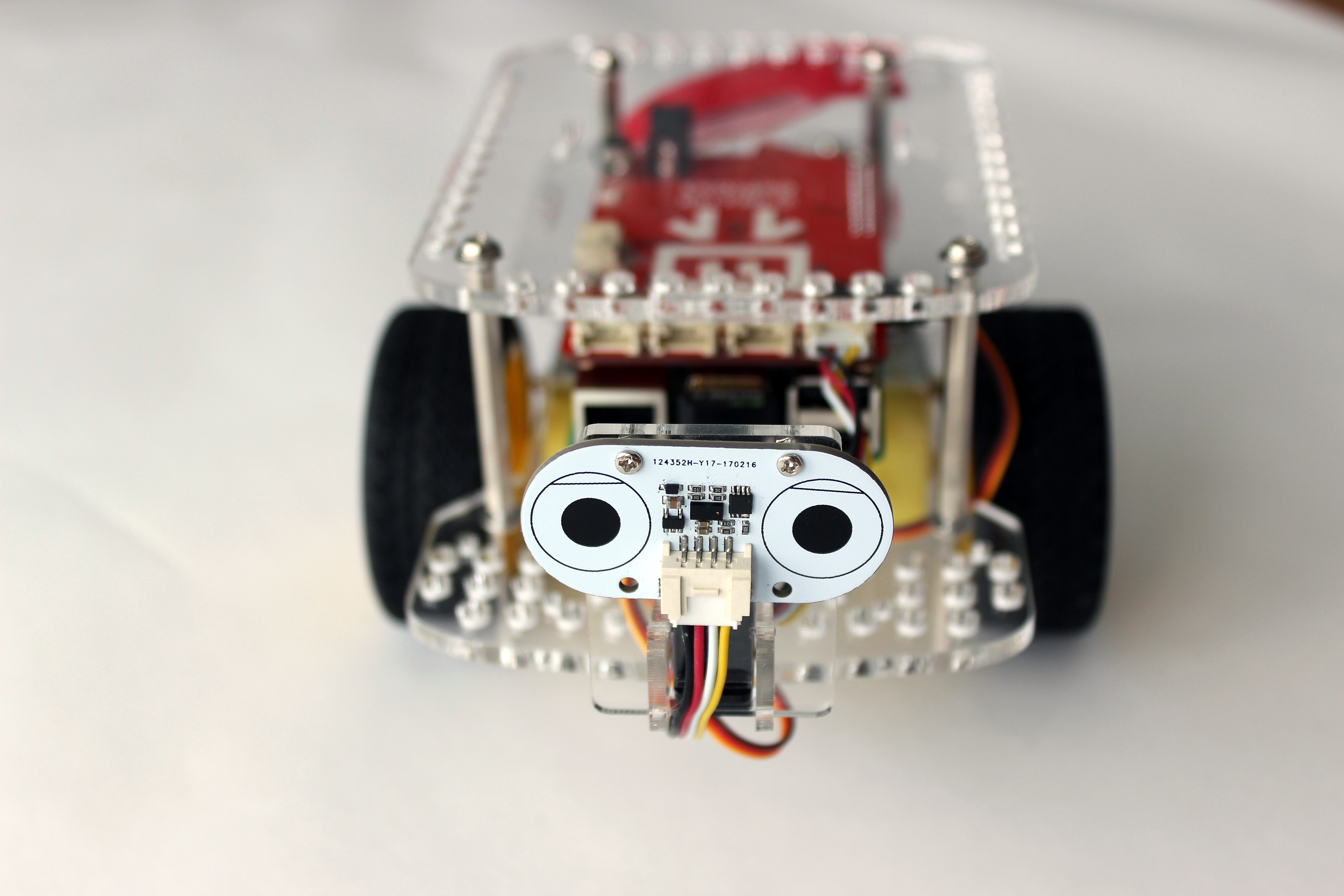
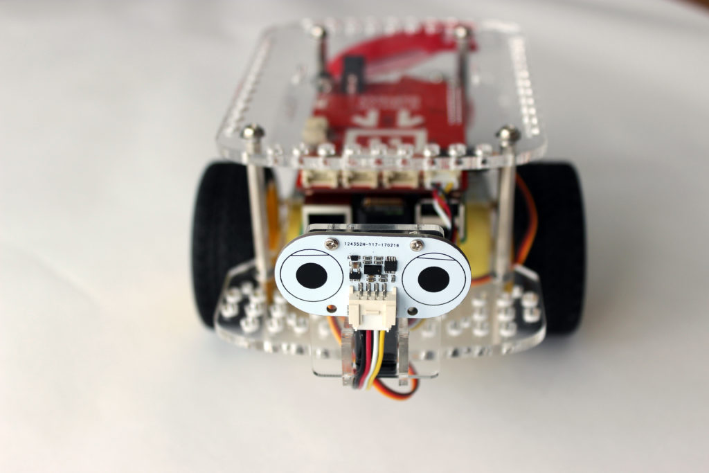
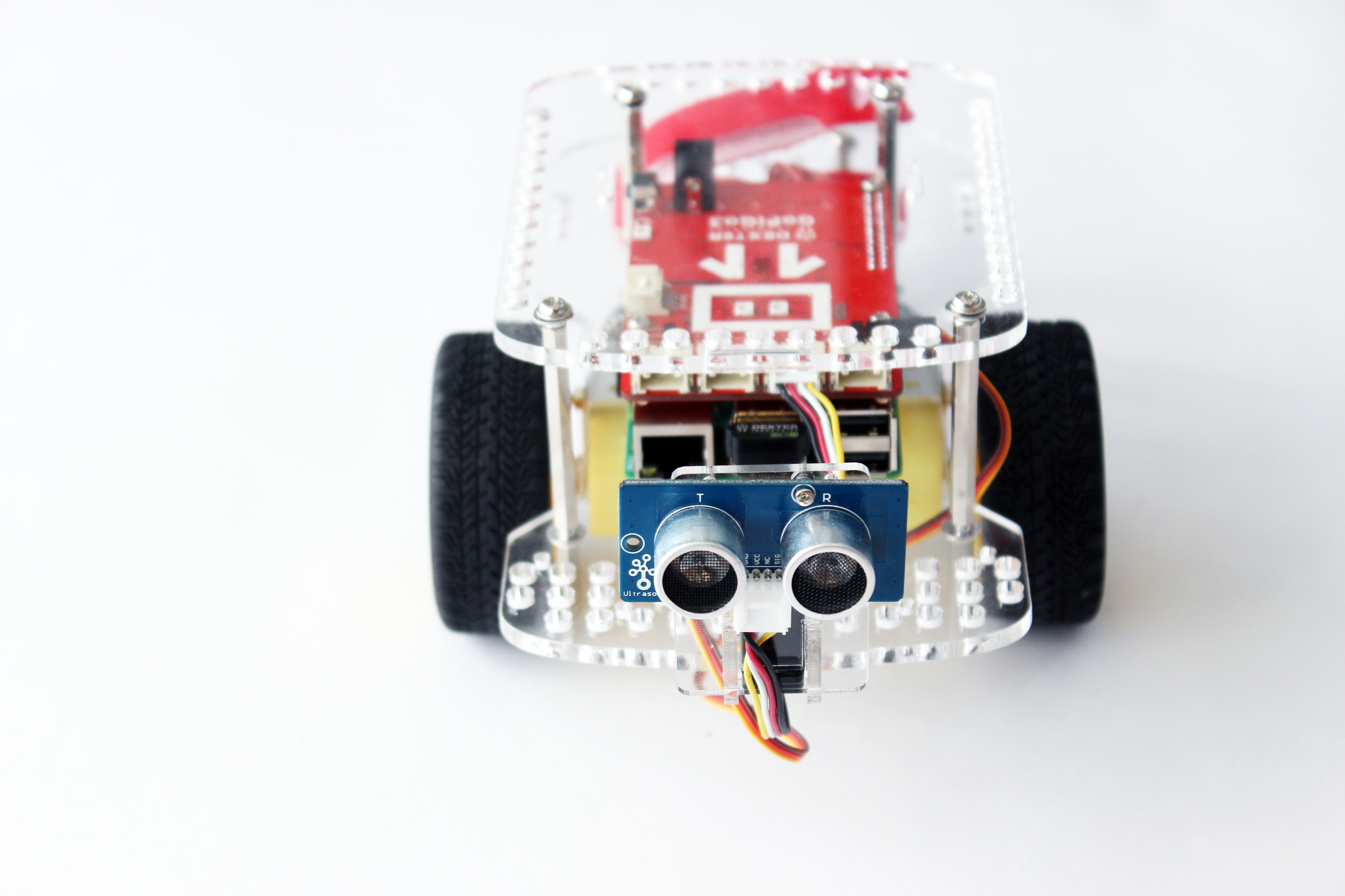
Attach the Ultrasonic Sensor
The Ultrasonic Sensor can be attached to the acrylic servo bracket.
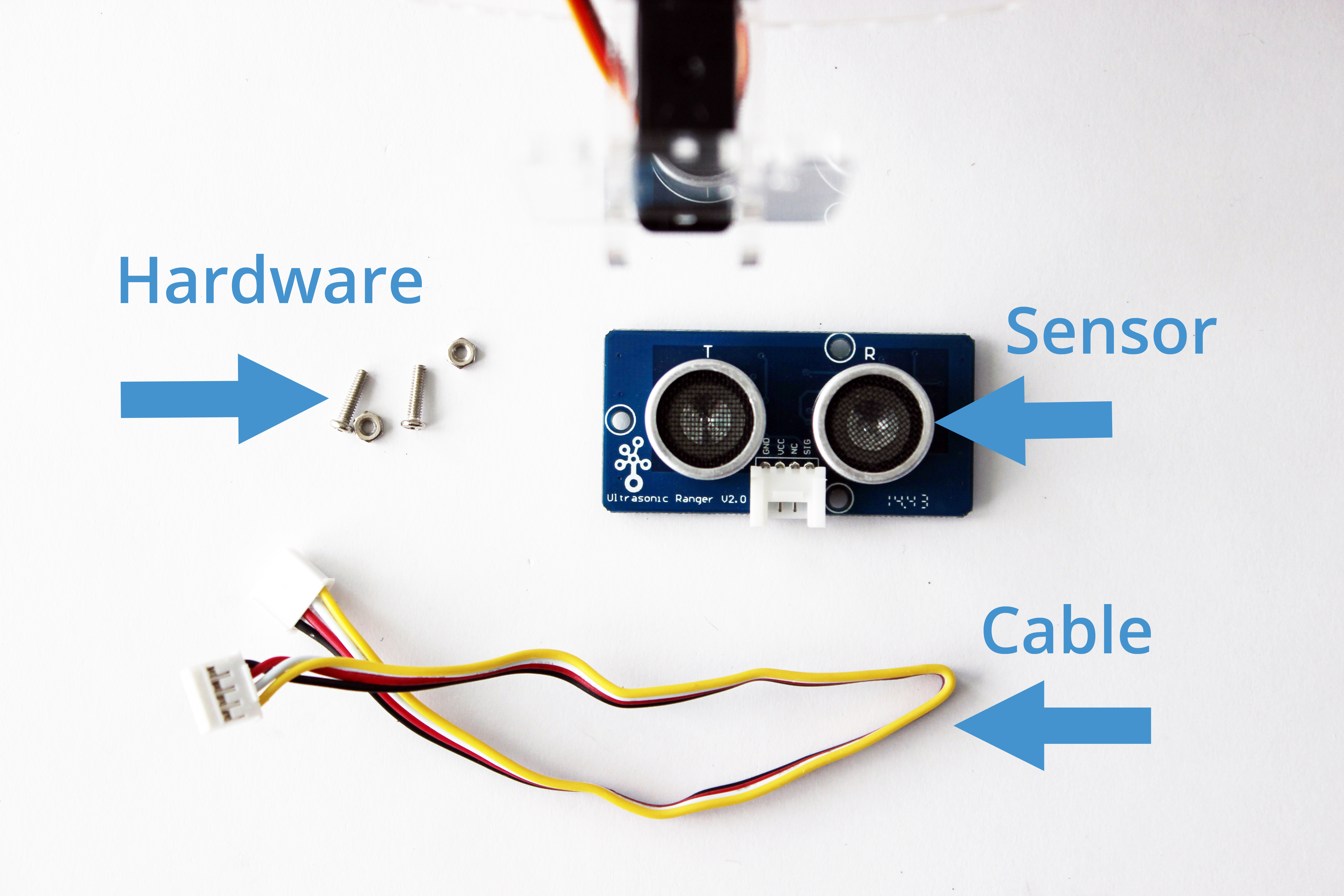
What you’ll need:
- Ultrasonic Sensor & cable
- Hardware from Servo Kit: 2 small machine screws, 2 nuts.
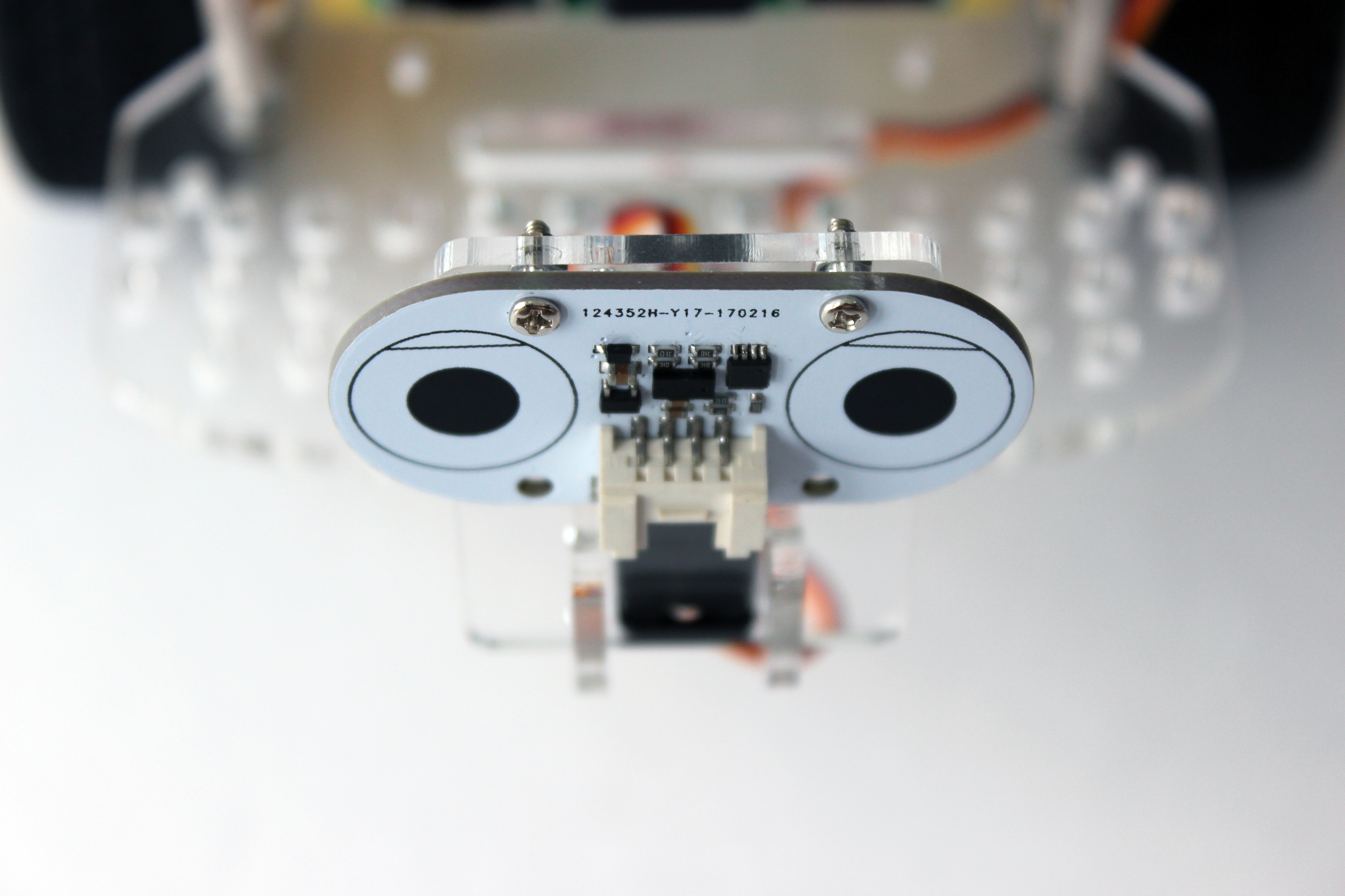
1. Locate the two vertically aligned holes between the two “eyes” of the ultrasonic sensor. Place two of the screws through these holes.
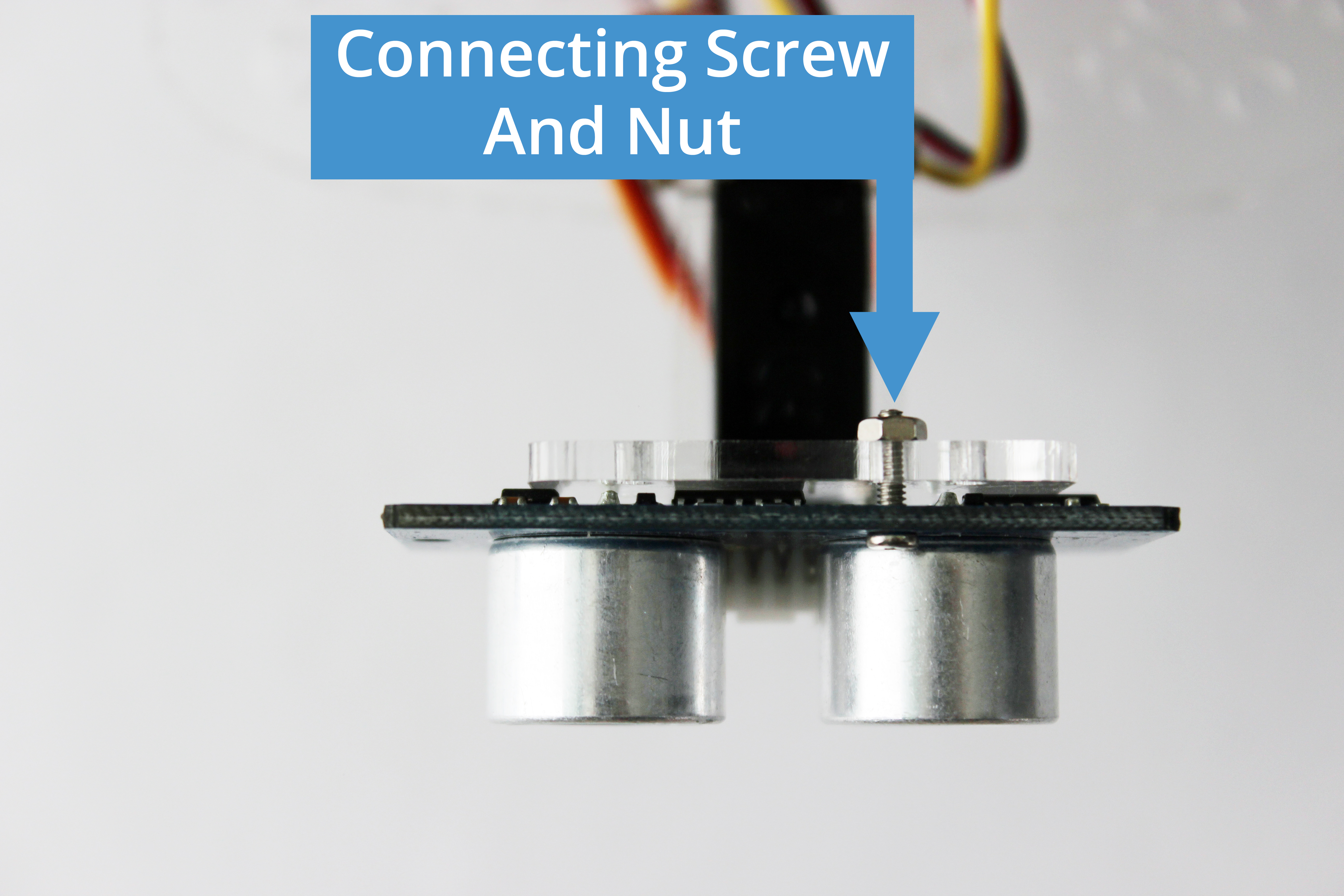
2. Slide the screws through the two holes in the middle of the servo bracket.
3. Place nuts on the back of the screws and gently tighten.
4. Connect the Ultrasonic Sensor to either of the ports on the GoPiGo3 labeled “Analog Digital 1” or “Analog Digital 2”.
Questions?
Go back to Get Started with the GoPiGo3.
Have a question or a suggestion? Ask on the forums here.