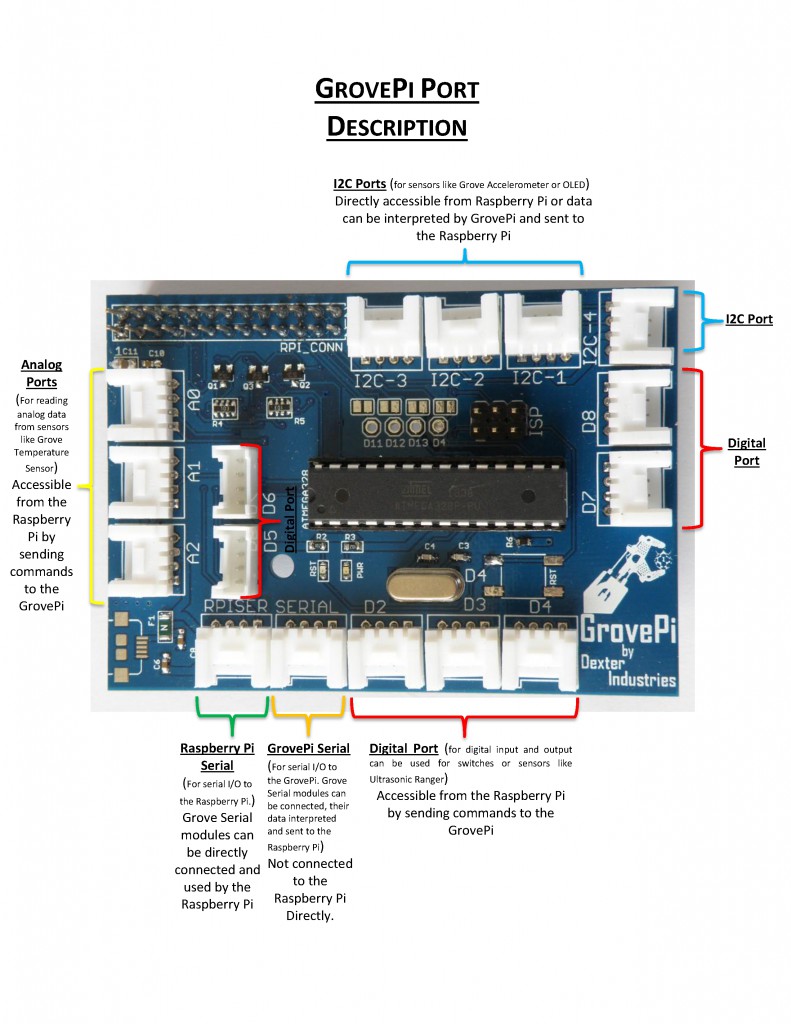
The GrovePi is stacked on top of the Raspberry Pi without the need for any other connections. Communication between the two occurs over the I2C interface. All Grove modules connect to the universal Grove connectors on the GrovePi shield via the universal 4 pin connector cable.
Grove modules, which work on analog and digital signals, connect directly to the ATMEGA328 microcontroller on the Grove Pi. The microcontroller acts as an interpreter between the Raspberry Pi and the Grove sensors. It sends, receives, and executes commands sent by the RaspberryPi.
In addition, the GrovePi enables the Raspberry Pi to access some Grove sensors directly. The Raspberry Pi has an I2C Bus and a Serial bus. These buses can directly connect to sensors via the I2C Ports and the USART Port.
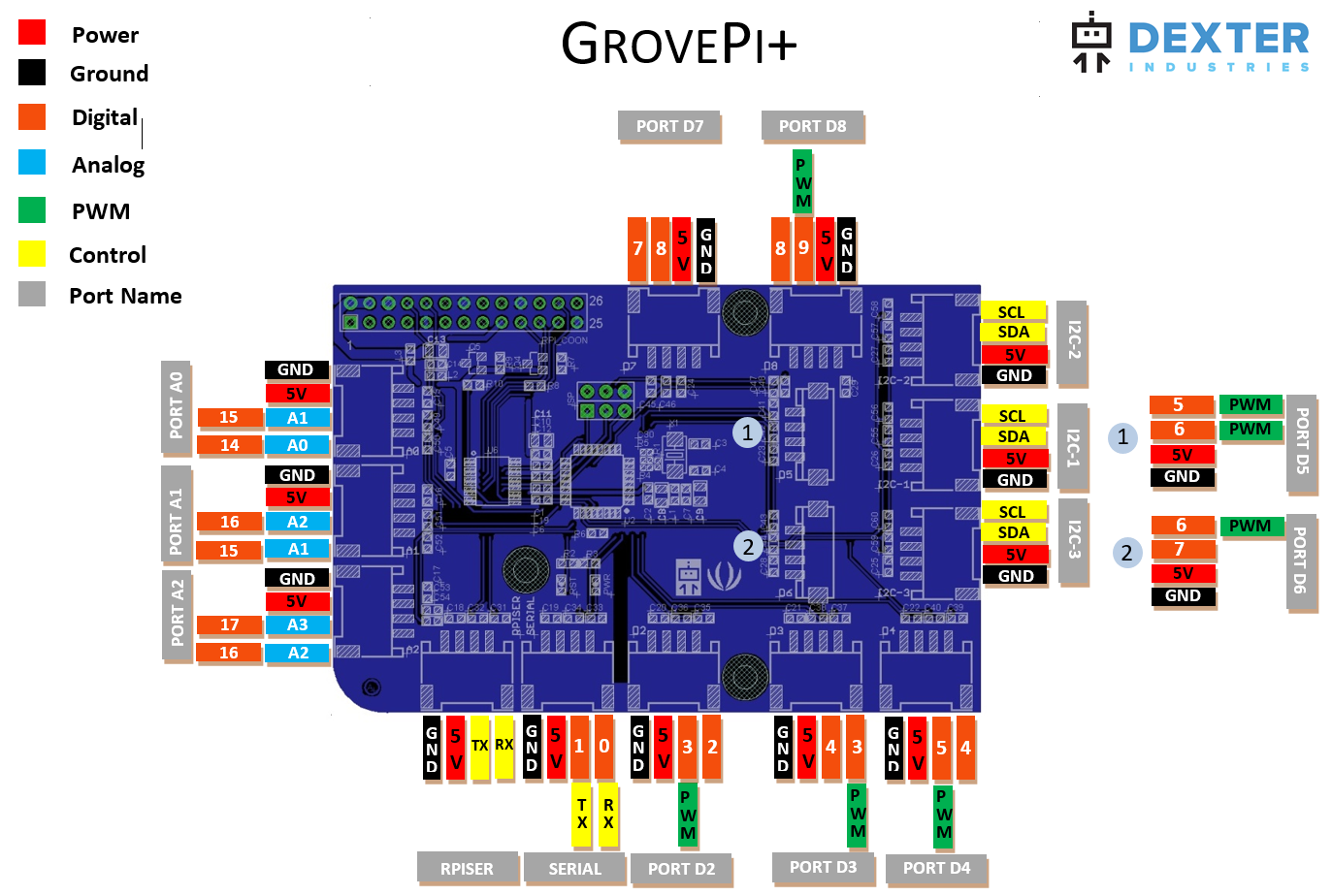
GrovePi+ Pinout – shows all the functions available on each port and how they can be used in software:
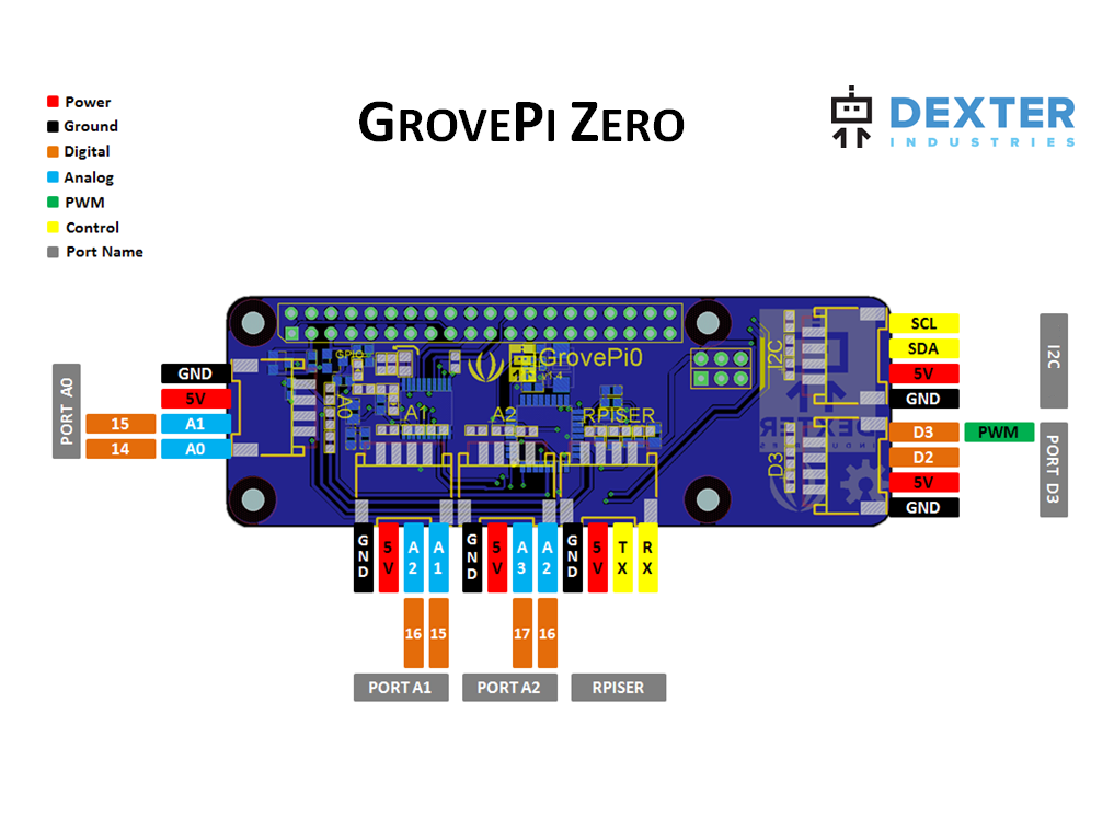
GrovePi Zero Pinout – shows all the functions available on each port and how they can be used in software:
mcauser from the GrovePi forums gave an excellent description of how the GrovePi Ports work:
The GrovePi runs an ATmega328 which contains an on-board 6 channel analog-to-digital (A/D) converter.
The AD converter has 10-bit resolution, returning values 0-1023.
Analog pins are usually used for reading analog sensors but can also be used for general purpose i/o, same as digital pins 0-13.
If you need more digital sockets, you can re-purpose an analog socket.
The pinMode() method is used to set the pin to INPUT orOUTPUT.
analogRead(2) and digitalRead(2) will read from different GrovePi sockets.
- grovepi.analogRead(2) will read from the socket labelled A2.
- grovepi.digitalRead(2) will read from the socket labelled D2.
On an Arduino Uno (same ATmega328 chip) the digital pins are marked as D0-D13 and analog pins A0-A5.
The analog pins are actually aliases for digital channels.
A0 = D14
A1 = D15
A2 = D16
A3 = D17
A4 = D18
A5 = D19
In an Arduino sketch, analogRead(A0) is the same as analogRead(14).
You can call grovepi.analogRead(0) or grovepi.analogRead(14)and you will get the same result.
GrovePi sockets A0,A1,A2 use the AD converter and supportanalogRead() values 0-1023.
GrovePi sockets D2-D8 are digital and support 1-bit input/output, values 0-1, using digitalRead() and digitalWrite().
GrovePi sockets D3,D5,D6 also support Pulse Width Modulation (PWM) which means you can write 8-bit values 0-255 with analogWrite().
Sadly you can’t use analogRead() with D3,D5,D6 and can only use it with A0,A1,A2 (aka D14,D15,D16).
grovepi.analogRead() uses the above aliases so if you are trying to read a value from an analog sensor connected to D3, analogRead(3) will actually read from the 2nd pin on the A2socket.
If you analogRead(pin) where pin is 0-5, it automagically adds 14 to the pin number to read the correct digital channel, where the AD converter exists.
So analogRead(2) will only read from socket A2, never socketD2.
And digitalRead(2) will only read from socket D2, never socketA2.
Why does the GrovePi not have any A3, A4 or A5 sockets?
Because I2C.
Channel A4 is used for SDA (serial data line) and channel A5 forSCL (serial clock line).
http://en.wikipedia.org/wiki/I2C
Ok, so why was an A3 socket not added to the board?
Socket A2‘s 2nd pin is A3 and an A3 Socket’s second pin would be A4.
You can analogRead() A3 if you have a 4 wire analog sensor, such as some of the analog accelerometers.
A4 is common with the I2C pins and would probably confuse people.
Why is there no D0 and D1 sockets on the GrovePi?
Because they are connected to the Serial port.
On the ATmega328, D0 is for RX (receive) and D1 is for TX(transmit)
TL;DR
grovepi.analogRead(0) - socket A0, read 0-1023
grovepi.analogRead(1) - socket A1, read 0-1023
grovepi.analogRead(2) - socket A2, read 0-1023
grovepi.analogRead(14) - socket A0, read 0-1023
grovepi.analogRead(15) - socket A1, read 0-1023
grovepi.analogRead(16) - socket A2, read 0-1023
grovepi.analogWrite(3,val) - socket D3, write PWM 0-255
grovepi.analogWrite(5,val) - socket D5, write PWM 0-255
grovepi.analogWrite(6,val) - socket D6, write PWM 0-255
grovepi.digitalRead(2) - socket D2, read 0-1
grovepi.digitalRead(3) - socket D3, read 0-1
grovepi.digitalRead(4) - socket D4, read 0-1
grovepi.digitalRead(5) - socket D5, read 0-1
grovepi.digitalRead(6) - socket D6, read 0-1
grovepi.digitalRead(7) - socket D7, read 0-1
grovepi.digitalRead(8) - socket D8, read 0-1
grovepi.digitalRead(14) - socket A0, read 0-1
grovepi.digitalRead(15) - socket A1, read 0-1
grovepi.digitalRead(16) - socket A2, read 0-1
grovepi.digitalWrite(2,val) - socket D2, write 0-1
grovepi.digitalWrite(3,val) - socket D3, write 0-1
grovepi.digitalWrite(4,val) - socket D4, write 0-1
grovepi.digitalWrite(5,val) - socket D5, write 0-1
grovepi.digitalWrite(6,val) - socket D6, write 0-1
grovepi.digitalWrite(7,val) - socket D7, write 0-1
grovepi.digitalWrite(8,val) - socket D8, write 0-1
grovepi.digitalWrite(14,val) - socket A0, write 0-1
grovepi.digitalWrite(15,val) - socket A1, write 0-1
grovepi.digitalWrite(16,val) - socket A2, write 0-1
Further Reading
- Arduino Analog Read
- Arduino Analog Write
- Arduino Digital Read
- Arduino Digital Write
- Arduino PinMode
- Arduino Analog Input Pins
- Arduino Digital Pins
- Stack Exchange Question on Arduino.
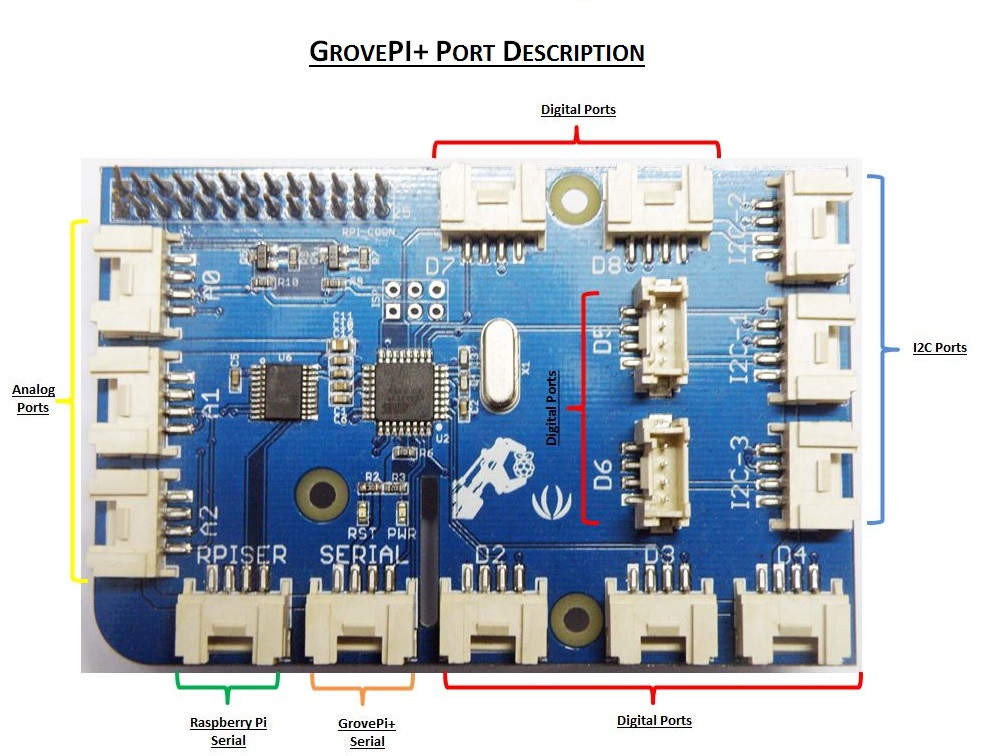
Older Schematics
Question?
Have a question or a problem? Post it on the forums and we’ll help you out.